How To Go From Schematic To Layout
By Rob Robinette
I have been asked many times if there is a book or webpage that describes how to go from an electronic schematic to creating an amp layout. I don't know of any so this is my attempt to explain my method.
Be sure and study the layout of popular amps that resemble what you want to build--there is a reason the designers laid out their amps the way they did.
You have to start with the physical characteristics of your desired chassis. If the chassis is going into a cab then you usually want the controls at the top of the cab which means the controls and inputs will go on one side of the chassis, the tubes and transformers will hang downward and the power cord and output jacks will be on the other side of the chassis. If the amp will be a "head cab" then you can put the chassis on the bottom of the cab and have the tubes and transformers standing upright. If the amp will be a desktop amp with no cab like your typical stereo audio amp then the tubes will point upward.
Bassman Micro Guitar Amp
AC power on the left side of the chassis and the sensitive first gain stage on the far right. The choke is less likely to pick up noise and hum so it is placed between the power transformer and output transformer.
Once you get that settled you need to layout the basics--the transformer and tube layout. Typically you want the power transformer and all the other AC related components such as the fuse, power switch and AC powered lights at one end of the chassis and have the sensitive first stage of amplification at the opposite end. The power supply components are also placed close to the power transformer.
The power and output transformer bells (and choke if used) should be out of phase to one another. In other words, if the bell of the power transformer is vertical then the output transformer bell should be horizontal to minimize interaction. Google "transformer headphone trick" for a method to find quiet transformer and choke placement.
You must consider where the circuit board will be placed when deciding on tube and transformer location--you don't want the board to cover tube sockets.
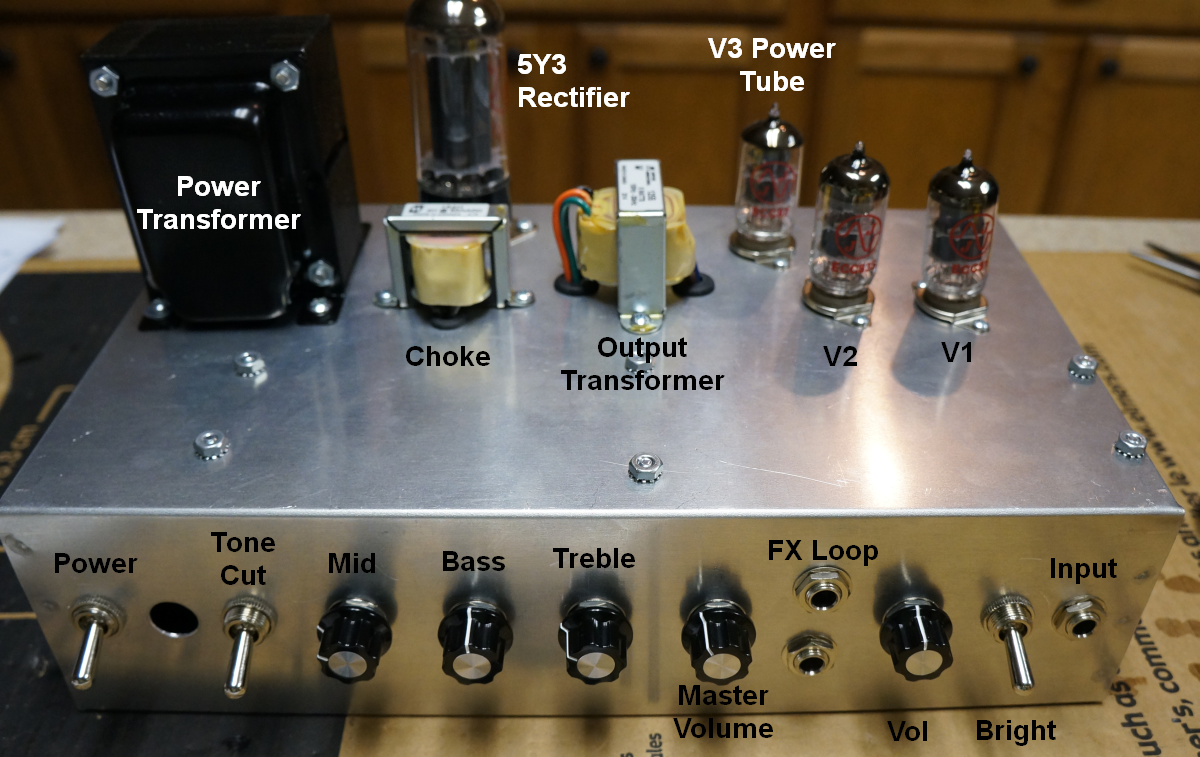
Notice how the simple Fender Champ amplifier below has controls and inputs on one side of the chassis, then the circuit board, then tubes and output jack on the other end of the chassis.
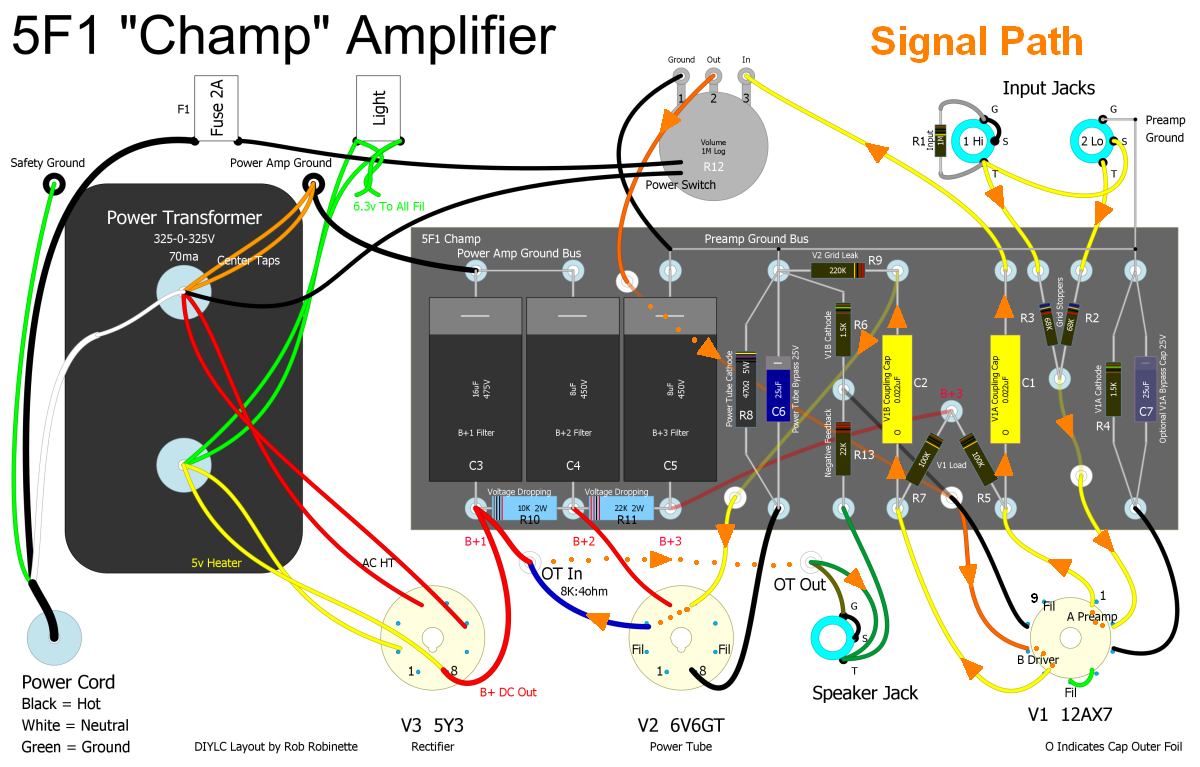
This layout was done using DIYLC (Do It Yourself Layout Creator) freeware.
The audio signal flows vertically, back-and-forth across the circuit board from input to circuit board to V1 tube, back across the circuit board to the volume control, then back to the V1 tube then back to the circuit board and finally to the power tube.
I like to start at one end of the chassis with the input jack and add components to the layout as I move through the signal flow and move toward the power supply end of the chassis.
Keep hot components such as power tube cathode resistors and power supply resistors away from other components, especially electrolytic capacitors. They can "cook" and dry out if they are too close to hot components.
You usually don't have to worry too much about interaction between components on eyelet and turret boards because of the natural component spacing but tightly packed PCBs can allow interaction. On PCBs try to keep high impedance signals such as tube plate connections and grids away from one another.
Try to design the circuit board layout for minimal wire crossing. Look at the layout above and see how the sensitive V1 tube socket leads don't have to cross one another--that design is intentional.
I use DIYLC (Do It Yourself Layout Creator) for my layout and schematic designs. It's freeware and it's worth the trouble to learn if you plan to do much design or modification work. It's easy to move and insert components and creates beautiful, high resolution .pdf and .png files. The components can be sized to match real world parts so you'll know your layout will actually fit when real components are placed on the circuit board and into the chassis.
References
RCA Corporation, RCA Receiving Tube Manual, RC30.
Merlin Blencowe, Designing Tube Preamps for Guitar and Bass, 2nd Edition.
Merlin Blencowe, Designing High-Fidelity Tube Preamps
Morgan Jones, Valve Amplifiers, 4th Edition.
Richard Kuehnel, Circuit Analysis of a Legendary Tube Amplifier: The Fender Bassman 5F6-A, 3rd Edition.
Richard Kuehnel, Vacuum Tube Circuit Design: Guitar Amplifier Preamps, 2nd Edition.
Richard Kuehnel, Vacuum Tube Circuit Design: Guitar Amplifier Power Amps
Robert C. Megantz, Design and Construction of Tube Guitar Amplifiers
Neumann & Irving, Guitar Amplifier Overdrive, A Visual Tour It's fairly technical but it's the only book written specifically about guitar amplifier overdrive. It includes many graphs to help make the material easier to understand.
T.E. Rutt, Vacuum Tube Triode Nonlinearity as Part of The Electric Guitar Sound