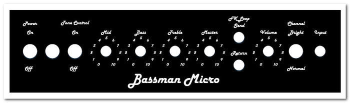
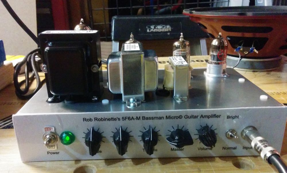
5F6A-M Bassman Micro© Guitar Amplifier
By Rob Robinette
Have comments or corrections? Email rob at: robinette at comcast dot net
Update: Jul 2022. I added a Lar-Mar/Type-2 Master Volume Bassman Micro layout.
Update: Dec 2020. I added an EF80 push-pull power amp option.
Update: Mar 2020. I added a 330k Normal Channel Load resistor for a better preamp gain match to the full size 5F6A Bassman.
Update: Jun 2019. I have made the Bassman Micro LTP the standard, recommended build. It's a much more faithful rendition of the 5F6A Bassman. Here's a youtube sound clip of the Bassman Micro LTP.
Update: Mar 2019. Due to builder feedback I moved the FX loop to reduce signal level. It is now placed immediately after the volume pot.
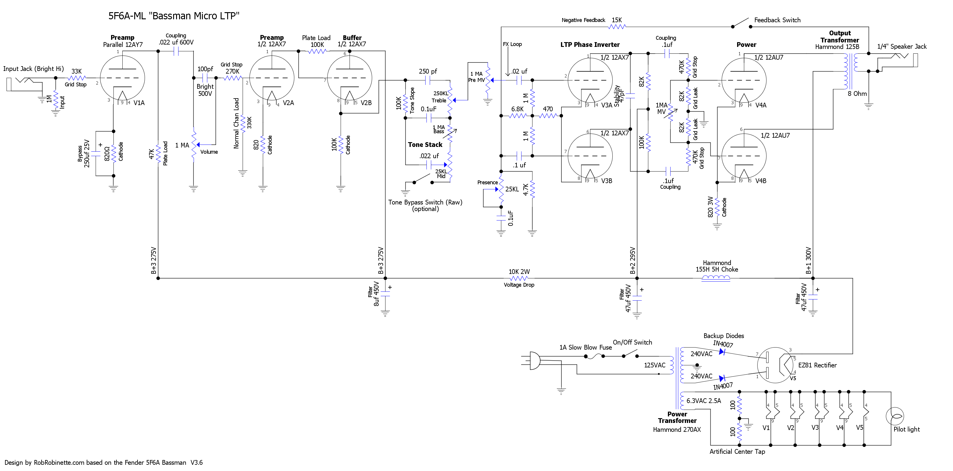
Update: May 2018. The Bassman Micro LTP layout and schematic were added. Using a Long Tail Pair phase inverter instead of a cathodyne allows the addition of a true 5F6A negative feedback loop and presence control. The overdrive tone is also more 5F6A authentic.
Update: April 2018. On stage with Circus Oz using a Bassman Micro
Update: April 2018. Bassman Micro builder Farrell Wymore recorded this song in the studio and used his Bassman Micro for all the guitar mixes: Collaborative by Farrell Wymore
Update: May 2017. Bassman Micro builder Reuben gigs with his amp. Here's a soundcloud of Reuben's Bassman Micro in the mix.
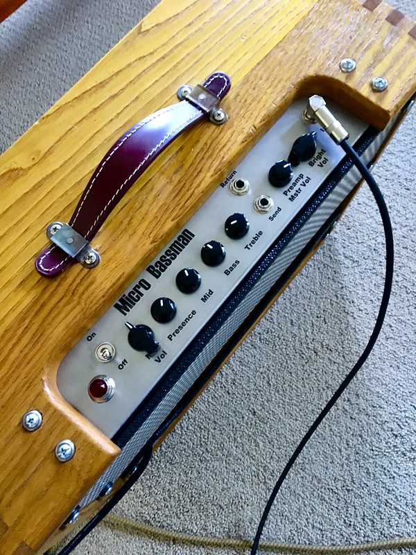
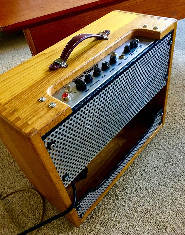
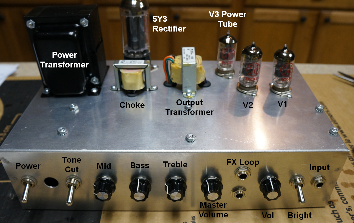
After the Deluxe Micro turned out so well I thought I'd take on a more ambitious project and build a Micro version of the legendary 1959 Fender tweed 5F6A Bassman. The Bassman Micro tube guitar amplifier is a compact practice amp that's moderately easy to build, uses three 12A*7 tubes and puts out 2 to 4 watts of output power. The Bassman Micro's single channel preamp circuit was inspired by the 5F6A Bassman's Bright Hi channel and the phase inverter is from the earlier 5E6A Bassman.
The Marshall JTM45 preamp is an exact copy of the 5F6A except for the use of a 12AX7 in V1 so this amp could also be called the JTM45 Micro. The Bassman Micro features two stages of gain, a tone stack buffer, tone stack with Treble, Mid and Bass controls, a cathodyne phase inverter and a true push-pull power amp.
WARNING
The Bassman Micro project utilizes full size amp, POTENTIALLY FATAL HIGH VOLTAGES. If you are unfamiliar with high voltage circuits or are uncomfortable working around high voltages, DO NOT RISK YOUR LIFE BY BUILDING THEM. Seek help from a competent technician before building any unfamiliar electronics circuit. RobRobinette.com DISCLAIMS ALL LIABILITY FOR INJURY OR PROPERTY DAMAGE RESULTING FROM THIS INFORMATION. ALL INFORMATION IS PROVIDED 'AS-IS' AND WITHOUT WARRANTY OF ANY KIND. See more tube amplifier safety info here.
Note: All of my amp designs, Blackvibe, JCM800 Micro, SLO-Nakid, Bassman Micro, RobRob Deluxe etc., are released under the Open Source Hardware Association license. You may build, modify and sell my designs without limit. For commercial use all I ask is that you include, "Design by RobRobinette.com" on your webpage and advertising.
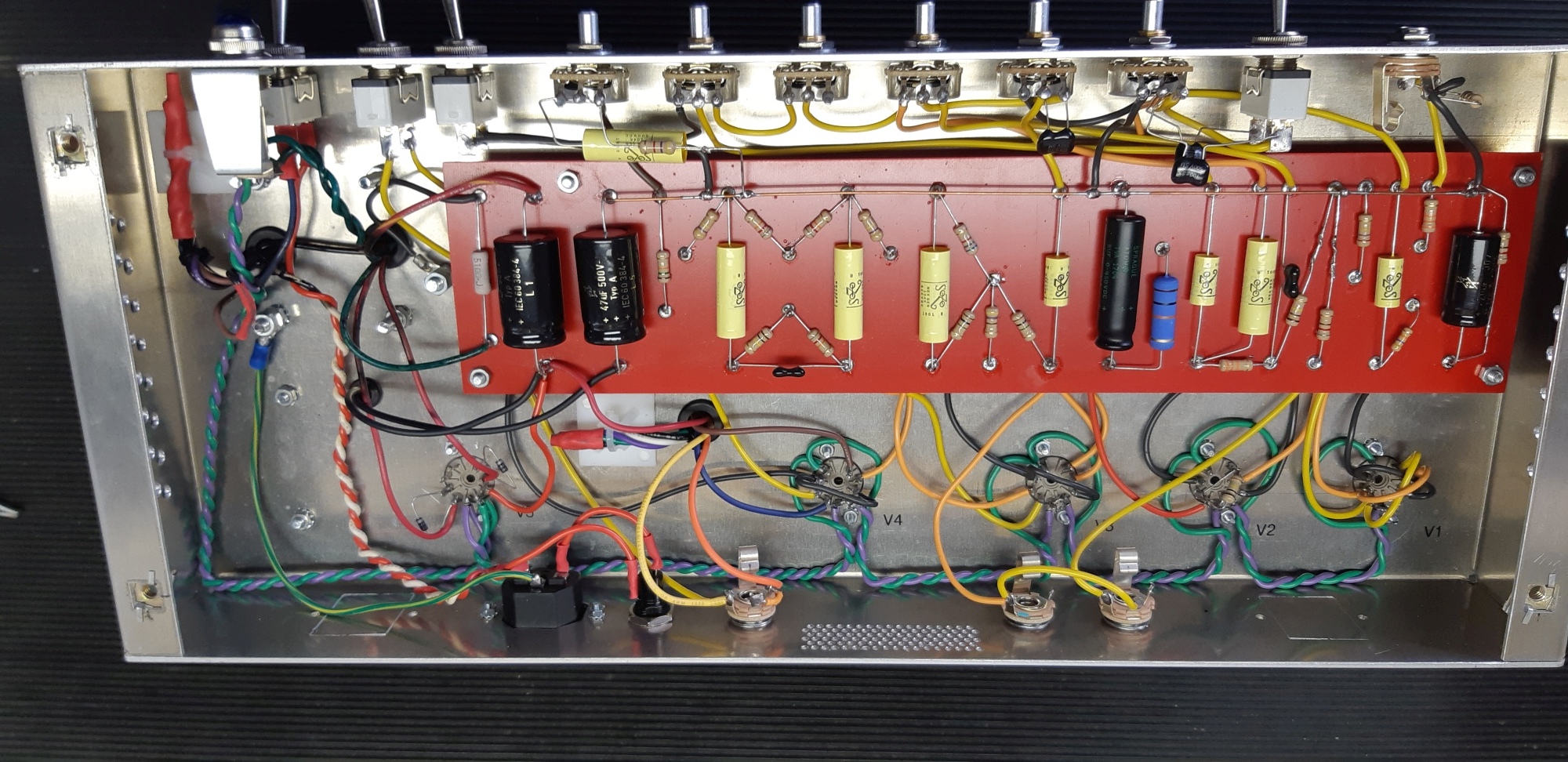
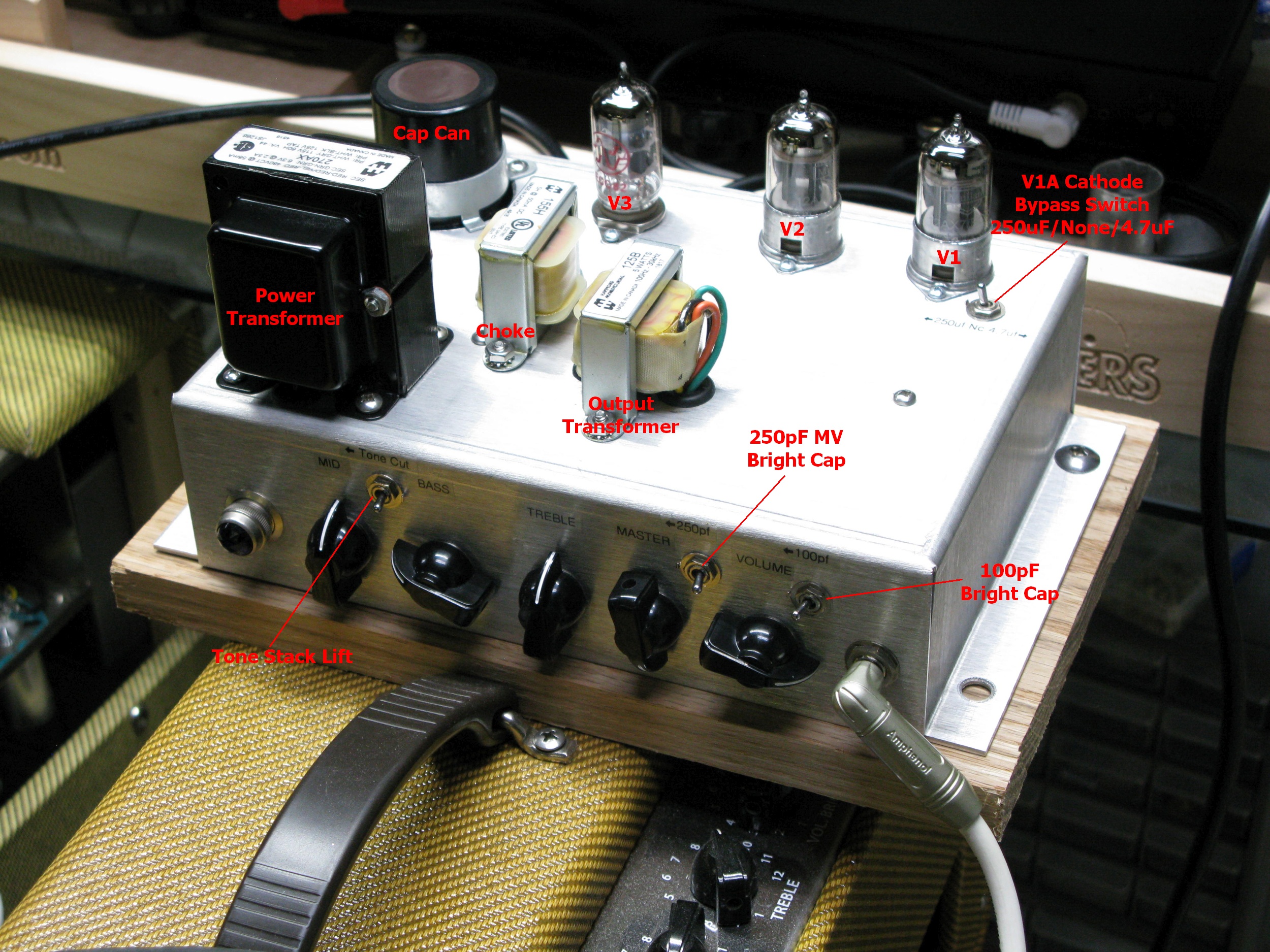
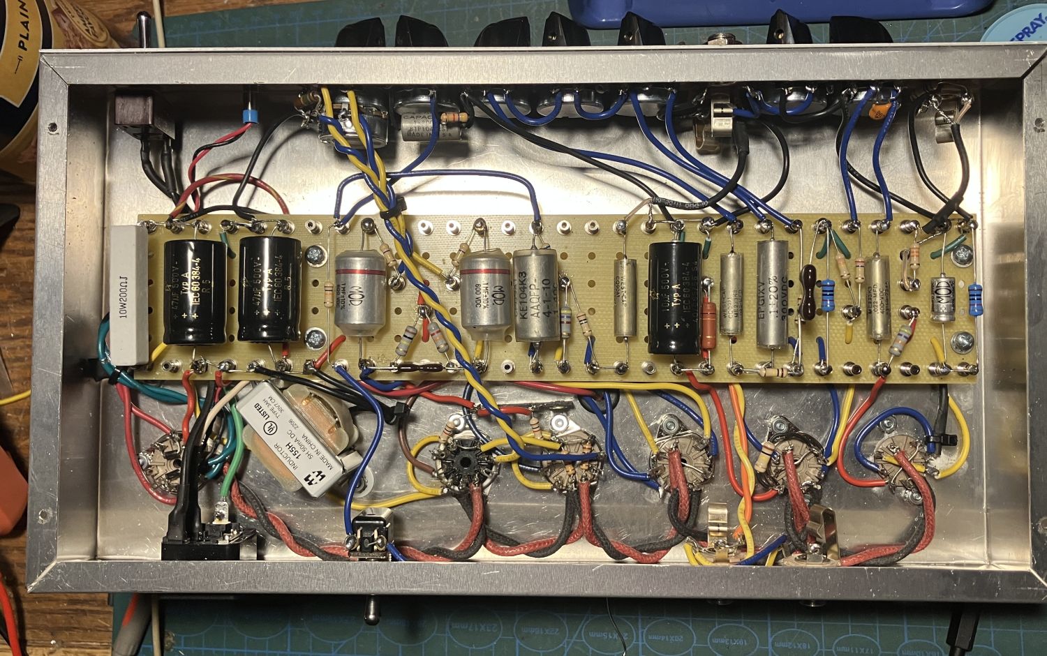
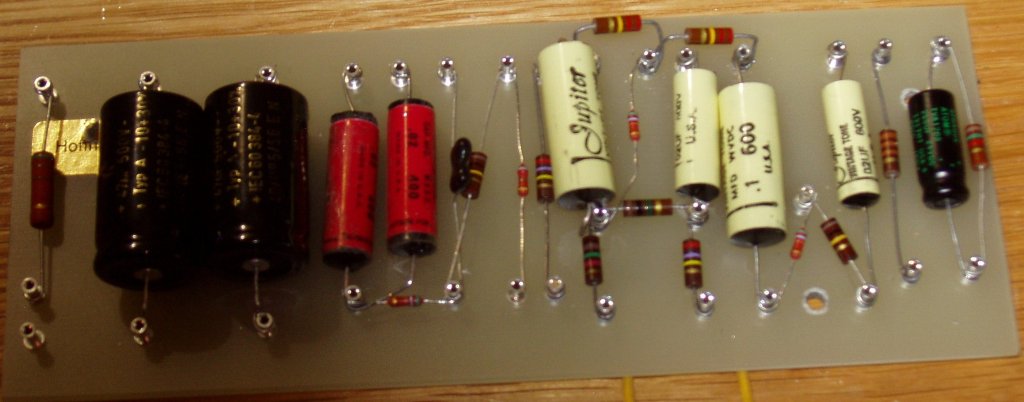
David Jones' Bassman Micro Circuit Board
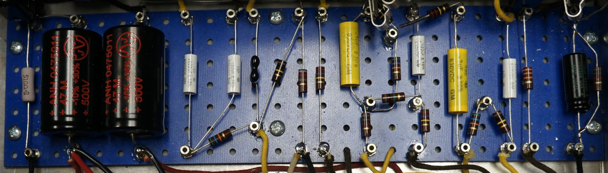
David used tube rectification so the diode rectifier is deleted from the extreme left edge of the board. Photo by David Jones.
Another Bassman Micro
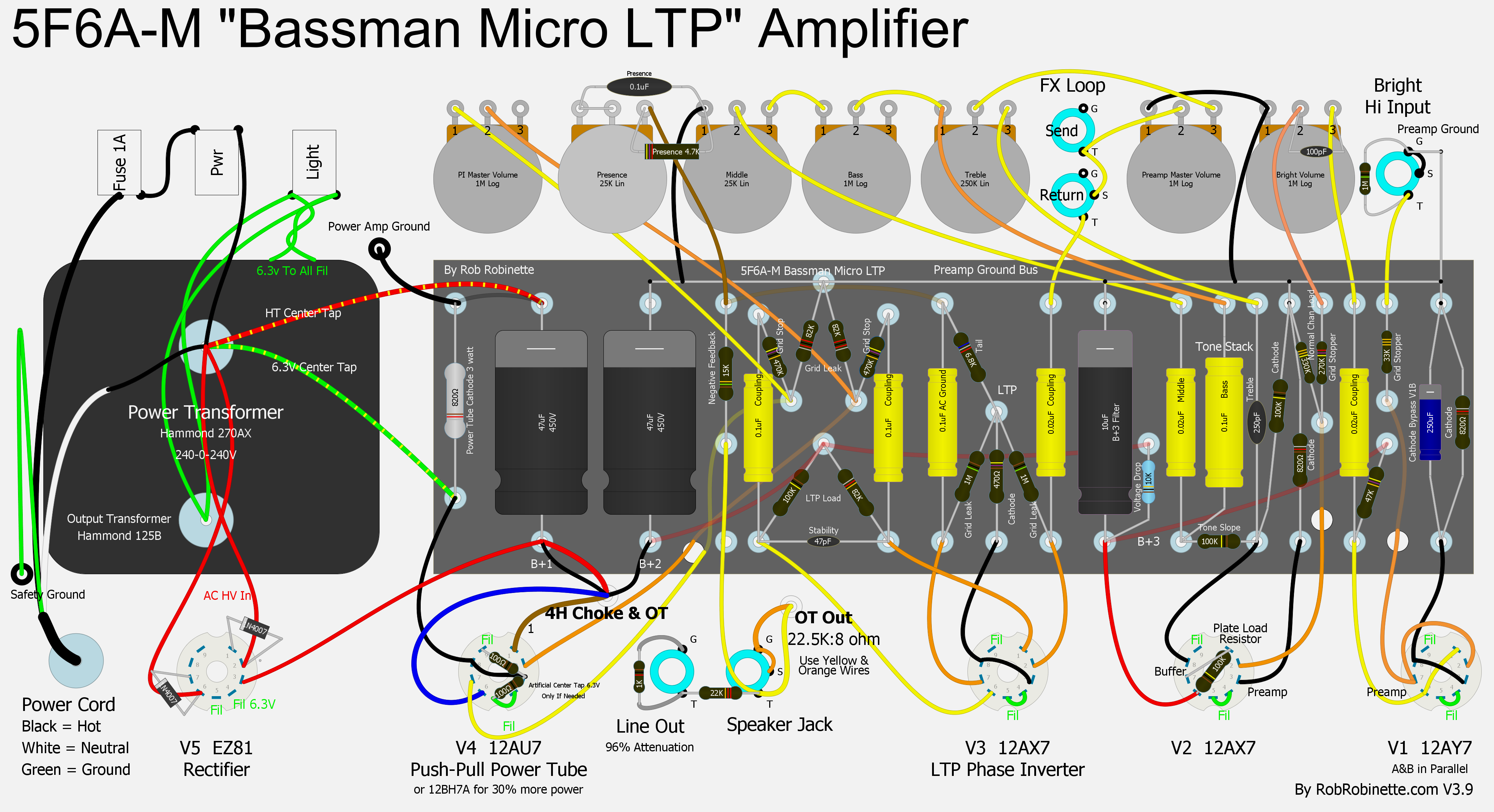
The 5F6A Long Tail Pair phase inverter, NFB and Presence circuits are used to replicate the famous 5F6A tone. The Post Phase Inverter Master Volume (far left control) can easily be deleted by removing the pot and its two wires. This layout shows a simple Type-3 master volume. The Type-2 master volume is more complex but works better. See the Type-2 master volume layout here. Click the image above to see the hi-res .jpg. Click here to see the hi-res Layout pdf file. Click here for the DIYLC Layout file.
Click the image to see the hi-res .jpg. Click here to see the hi-res schematic pdf file. Click here for the DIYLC schematic layout file.
Bassman Micro LTP Demo
Bassman Micro LTP by Hervé Duport
Photos and build by Hervé Duport
Dan Miller's Bassman Micro Head and 4x10 Cab
Dan used a Hammond 12x7x3 aluminum chassis.
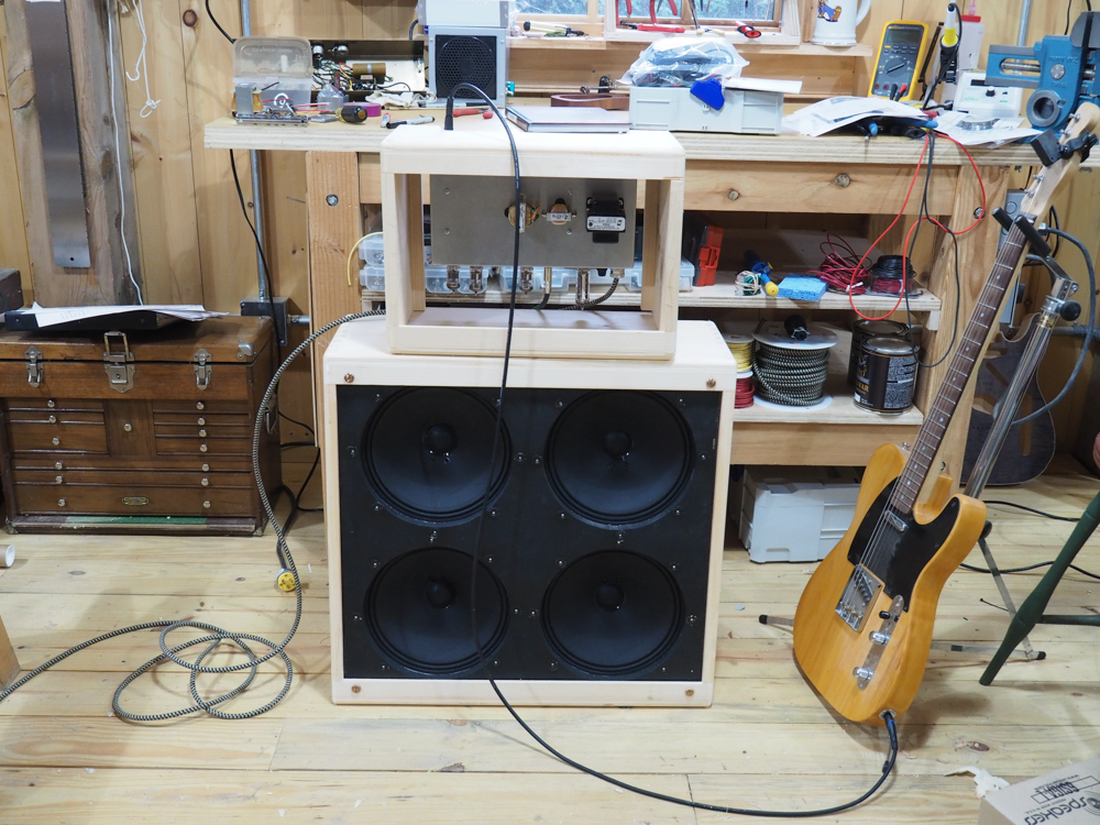
Photos and amp build by Dan Miller.
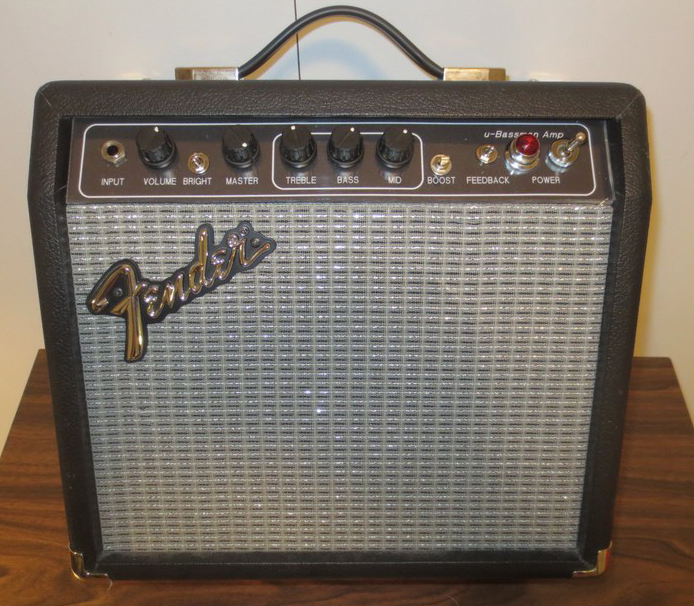
David Jones' Bassman Micro
Faceplate design, amp build and photos by David Jones.
dubulup Bassman Micro
Photos by dubulup.
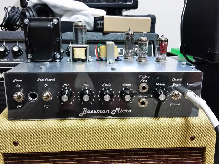
Mike Millard's Bassman Micro LTP
Photos and amp build by Mike Millard.
Design
I'm a big fan of the 1950's Fender tweed amps and the 5F6A Bassman is a legendary amp that was copied by Marshall and became the foundation of that company's amp lineup. I built a 5F6A head amp and it's the sweetest sounding amp I've ever heard so I decided to design a Micro version of The Bassman. I used an almost exact copy of the Bassman's Bright Hi preamp channel and Long Tail Pair phase inverter feeding a small bottle true push-pull power amp.
I liked the output and flexibility of the 12AU7/12BH7 tubes for the true push-pull power amp. The 12AU7 with both triodes in push-pull will develop around 1 watt of output power. Swap in a 12BH7 and the output increases to around 2 watts. My H&K Tubemeister 5 uses a 12BH7 in push-pull and it sounds very good. The 12AU7 and 12BH7 tubes are very similar in output tone but the volume boost from the 12BH7 is noticeable at around 30% more power. Both tube types are readily available with the 12BH7 going for about $5 more than a 12AU7.
One of the reasons I chose to use the Fender 5F6A tweed Bassman preamp in this project is the Marshall JTM45 uses an exact copy of the circuit except Marshall calls for a 12AX7 in V1 instead of the Bassman's lower gain 12AY7. All that's required to convert the Bassman Micro into a JTM45 Micro is to put a 12AX7 in V1. A 12AX7 in V1 gives you much more overdrive and pushes the Bassman Micro's tone into the 1960's.
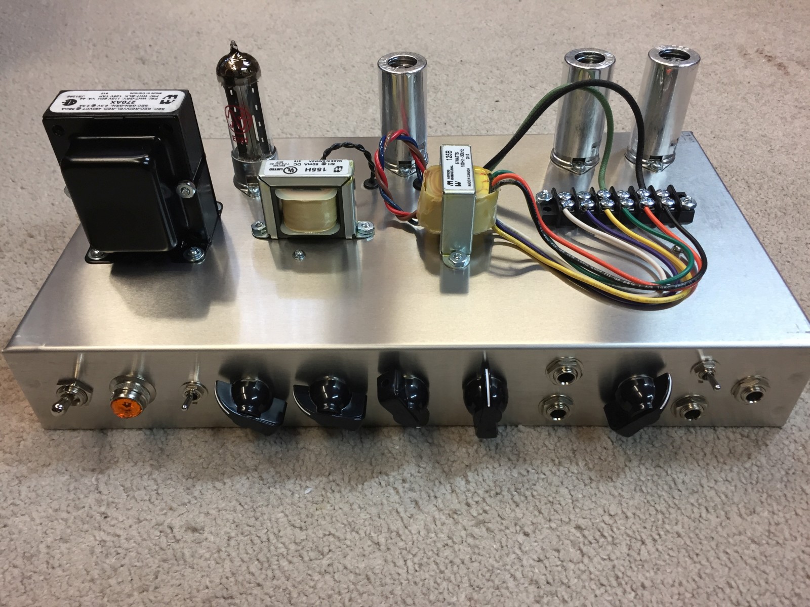
I went with a small, 5 Henry 50 milliamp Hammond 155H choke to filter the B+ for the entire amp.
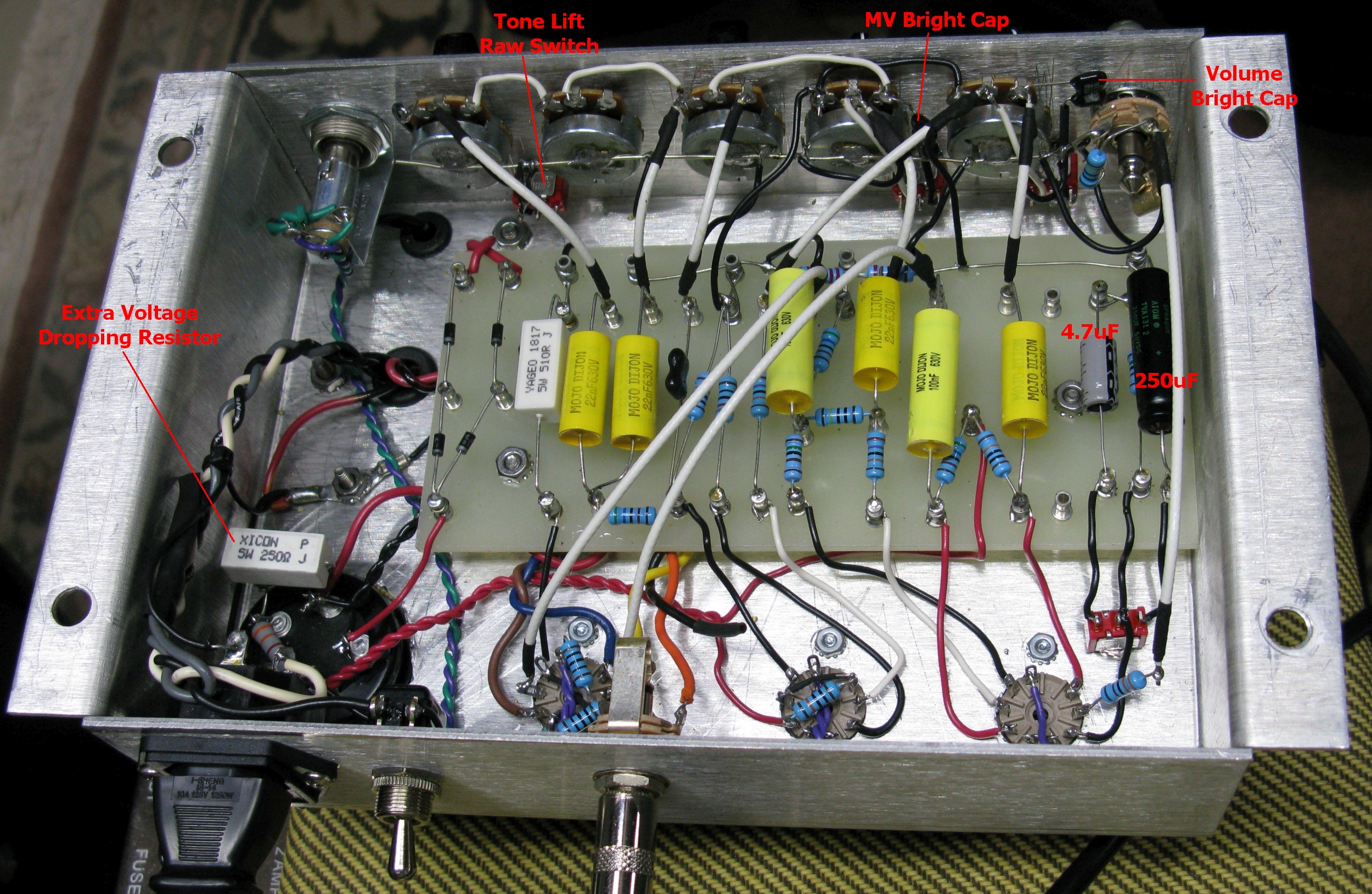
I designed in a Bright/Normal Channel Switch because the only difference between the 5F6A's channels is the Bright Cap. By putting it on a switch you can choose between the Bright and Normal channels. The difference between Bright and Normal is very subtle with the 5F6A's 100pF bright cap but you can make it more effective by increasing the value to 500pF (or 470pF).
I added a 330k Normal Channel Load resistor to mimic the load placed on the Bright Channel by the Normal Channel. Without this load resistor our preamp gain will be much higher than the 5F6A. The original Bassman's 220k Bright Channel Mixing resistor forms a voltage divider with the Normal Channel load so adding the 330k load resistor gives us the same preamp gain as the dual channel 5F6A. Deleting the 330k Normal Channel Load resistor will significantly boost preamp gain if you are into that. You can also put the load resistor on a switch (open switch = no resistor = gain boost).
The Tone Stack Bypass (Raw) Switch is an easy mod that removes the signal sucking tone stack from the circuit and delivers "raw" guitar tone. The signal will be 'boosted' and 'naturalized' when the tone stack is bypassed. This switch also comes in handy if you like to use an equalizer pedal for tone shaping. An excellent alternative to the Raw Switch is just using a 100KA pot for the Mid tone control instead of the standard 25KL pot. The 100KA (yes, audio taper) pot will allow you to gradually roll on more preamp gain and mid freqs instead of having the all or nothing of a raw switch.
Bill Bock's Bassman Micro
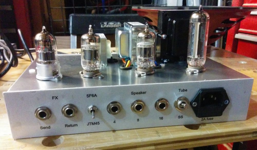
The "poor man's FX loop" allows you to insert post preamp effects. The Master Volume acts as the FX 'send volume' so you can feed your true 5F6A Bassman preamp into a PA or soundboard. You can also tap directly into the power amp by inserting a signal from a modeling preamp such as a POD HD500 directly into the Return jack (guitar > HD500 > Return Jack) but since you are bypassing the preamp and volume controls you must control the amp's volume with the FX or guitar volume.
The power amp grid stop and grid leak resistors are arranged as an attenuating voltage divider to get the signal voltage down to suit our little power tube(s).
You have the choice of using a simple solid state, 9-pin or 8-pin tube rectifier. I recommend you use an EZ81 9-pin rectifier tube because it's low output will suit the low current needs of the Bassman Micro so you'll get a little voltage sag. The EZ81 will drop about 20 volts compared to a solid state rectifier. It uses a standard 9-pin socket and 6.3V filament heat so no 5V power transformer output is needed. If you want to use a full size 8-pin rectifier tube like a 5Y3GT which drops about 60 volts compared to a solid state rectifier then I recommend the higher voltage output Hammond 270CAX power transformer to compensate for the extra voltage drop. It comes with a 5V output for the 5Y3. Just wire the 8-pin socket with the high voltage to pins 4 and 6, 5V heater lines to 2 and 8 and the B+ power output wire to pin 8.
Development
My recommended power transformers are the Hammond 270AX for the US and Hammond 370AX (available here) for international builders (has 100, 110, 120, 200, 220 and 240 volt primaries, see this for wiring instructions). They have 240-0-240V high voltage secondary output and 6.3V heater output. If you use solid state rectification you may need to add a 2 watt voltage dropping resistor before the first filter cap to bring the voltage down to around 315V DC at the first filter cap.
The recommended output transformer is the Hammond 125B (or 125C for less compression and more volume but I believe the 125B will give the truest 5F6A tone). Use secondary wires 2 & 4 to give 22500:8 load impedance for 8 ohm speaker.
The 12AY7, 12AX7 and 12AU7 all use 0.3 amps of 6.3v heater current. If you use an EZ81 rectifier tube it uses about 1 amp of heater current so any power transformer that supplies 2 amps of 6.3v for tube rectification will work.
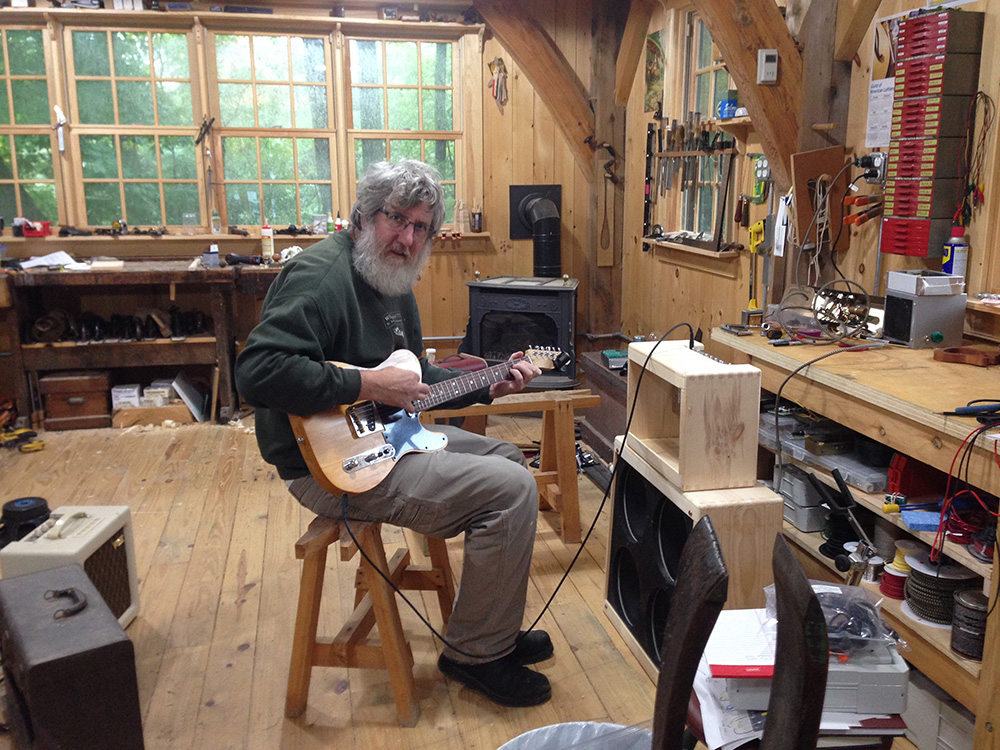
Test and Tweak On the Prototype Bench
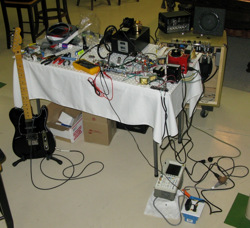
Red variac controls just the high voltage AC to the amp. Separate 6.3V transformer supplies heater current. During the test and tweak phase of development I compared the Bassman Micro to my 5E3P Deluxe (top right in tweed cabinet), my Deluxe Micro, a Firefly micro amp (just left of the red variac) and an H&K Tubemeister 5 (on top of the Deluxe). I played them all through a Weber 12A125A 12" Alnico speaker in an open back extension cab (behind table), a 15" JBL E130 with hemp cone (in the 5E3P cab) and an Eminence 620H hemp coned 6" speaker in a small enclosure (on top of the Deluxe). The blue box at bottom right next to the oscilloscope is a bucking transformer used to lower the heater voltage to spec.
I added a Master Volume to the power amp because it's needed to control how hard the little 12AU7 power tube is driven. The Master Volume also does a good job of controlling the output for true bedroom amp volume levels. The Master Volume is also very helpful when pedals are used with the amp because you can keep from overwhelming the little power tube when using high output FX.
You need to play with the Master Volume to get the most out of this amp and to control the balance of preamp and power tube distortion. The Volume pot controls the preamp tube and the Master Volume controls the power tube. Some high output guitar pickups and effects pedals can push the power tube too hard and cause some funky power tube blocking distortion. If this occurs just dial back the Master Volume a little.
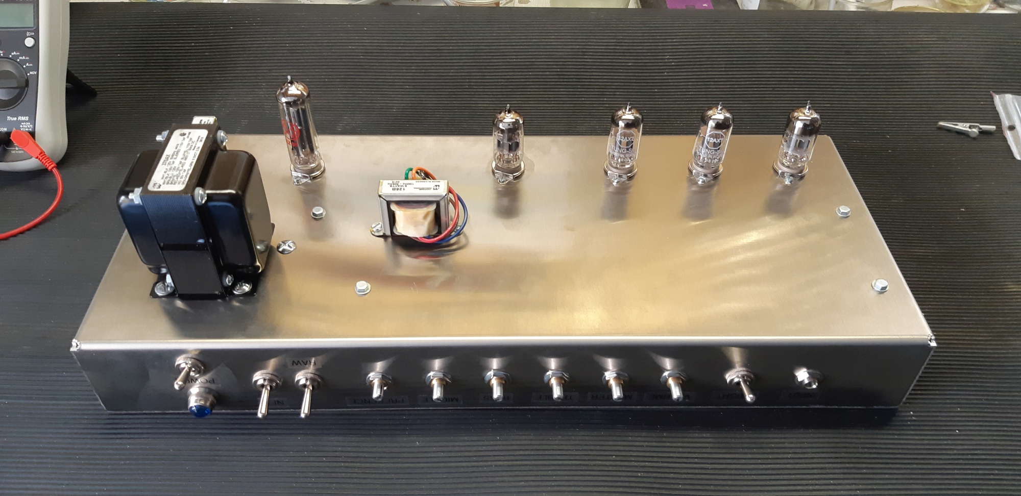
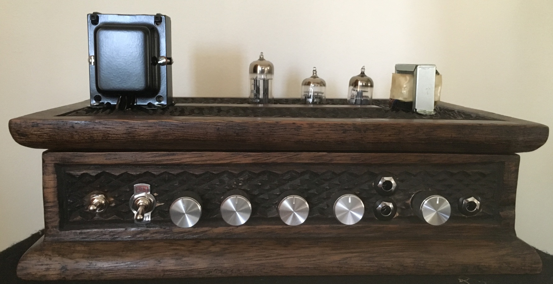
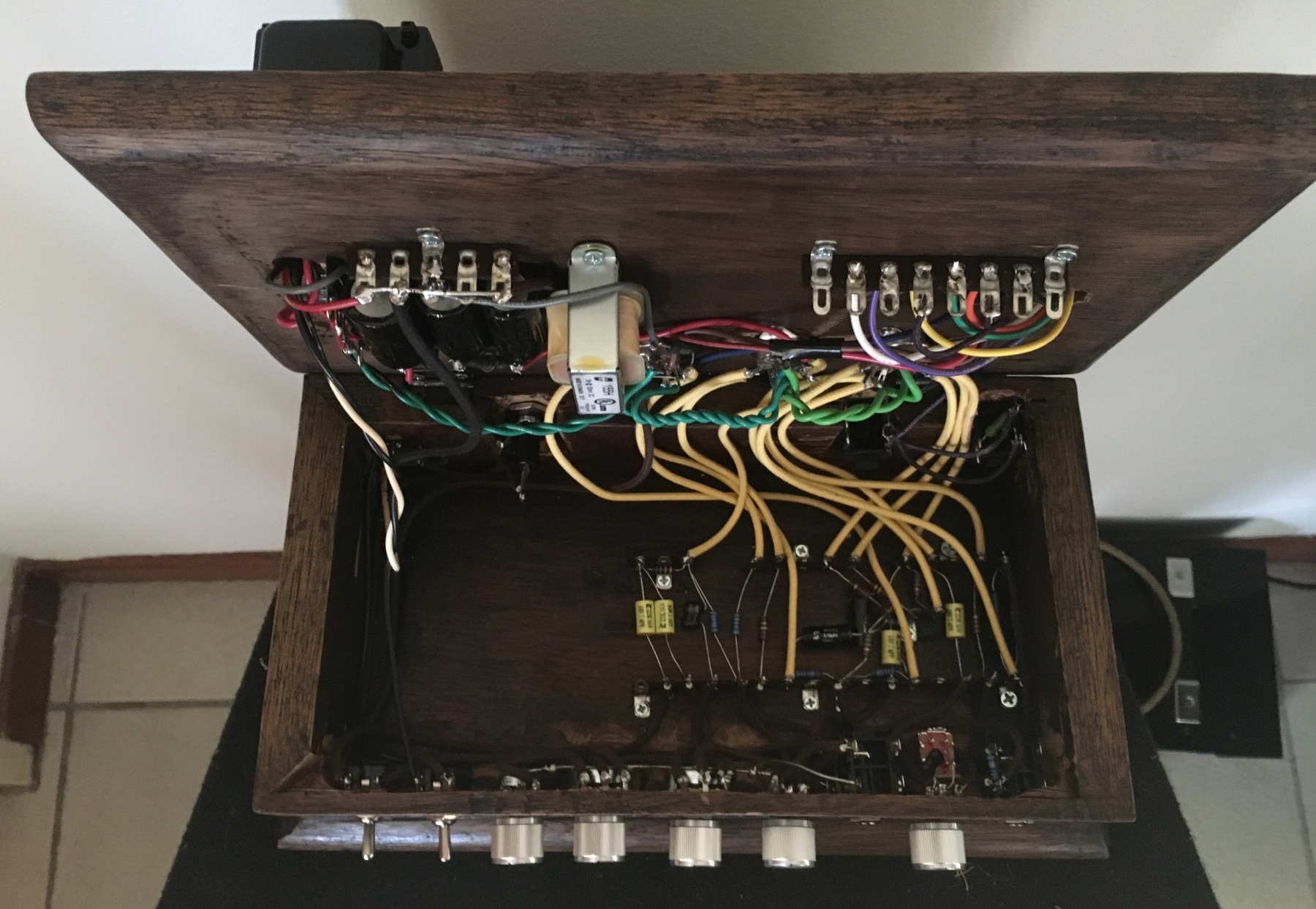
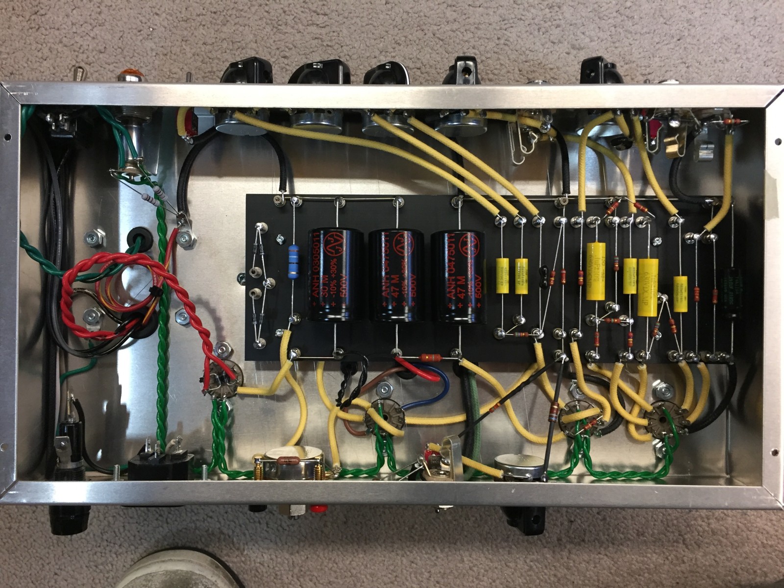
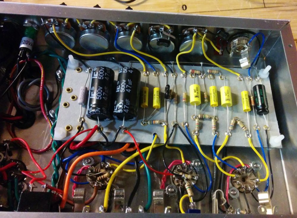
Bassman Micro Interior Chassis
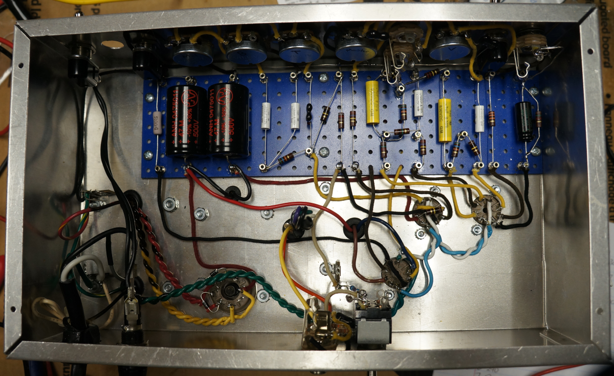
Photo by David Jones
Doug Hoffman at HoffmanAmps.com can make you a Bassman Micro LTP turret or eyelet board using this Bassman Micro LTP Hoffman file for about $20 + shipping. Just go to the HoffmanAmps DIYLC Analyzer page and upload the Bassman Micro LTP Hoffman file.
I have an Electro-Harmonix 12AY7 in V1, Tung Sol 12AX7 in V2 and an EH 12AU7 in V3. I've heard great things about the long plate JJECC802S 12AU7 as a power tube so give it some consideration. I typically set the Bass control low at about 3 and leave it alone and then play with the amp's two volume controls--don't set the Master Volume and forget it, it has a lot of affect on the amp's tone. When you want to really turn up the overdrive try a 12AX7 in V1 which converts the amp into a Marshall JTM45 Micro. The Bassman Micro handles a 12AX7 in V1 well because the Master Volume can keep the little power tube from being overdriven into oblivion. I'm really surprised all micro amps don't have a Master Volume, it really is necessary to make a micro bottle power amp versatile.
Here's an mp3 sound clip of David Jones playing his Bassman Micro. He said this about the clip:
For the dirty sounds I set the volume to about 3 o'clock and the master volume to about 10 o'clock. For the clean sound I set the master volume to max and the volume to about 10 o'clock. Bass, Treble and Mid were all set to 12 o'clock. I had the feedback switch in the middle position (off).
I played the Bassman Micro through three different speakers during testing: My favorite Fender tweed era speaker is the Weber 12A125A 12 inch Alnico in an open back cab. The little Bassman Micro sounded best with this pairing--very rich and tweedy and it made my Telecaster sound like a Tele should. The 12A125A is a low efficiency speaker rated at 95dB but the Bassman Micro still put out plenty of volume at high Master Volume settings.
I also tried my favorite small speaker, an Eminence 620H 6 inch hemp coned speaker. If you need lower volume this little speaker is the way to go. It still sounds very good with less of everything compared to the Weber but max volume is quite a bit lower.
Finally I hooked up my 5E3P Proluxe's 15 inch JBL E130 hemp coned speaker to the Micro. It's a very high efficiency (105 dB) driver that pumps out loud, clear, accurate guitar tone. The Bassman Micro was crazy loud and sounded fantastic. I really had fun with this speaker for high distortion shredding with a 12AX7 in V1 but it was loud enough that my wife had to intervene. I recommend you go with an 8" or larger speaker because this amp sounds too good to be strangled by a 6" speaker. Bottom line is any speaker that works with a full size tweed amp like the Deluxe or Bassman should work well with the Bassman Micro.
I compared the Bassman Micro's tone to my Firefly micro amp (single self-split push-pull 12AY7 power tube) and H&K Tubemeister 5 (push-pull 12BH7 power tube). The biggest difference in tone is the Bassman Micro's low end. It's always there no matter how hard you shred the little amp, while the Firefly and Tubemeister scream with modern high pitched accuracy. You could really hear the difference between the two amps through the big 15" JBL but the Bassman Micro blows away the other amps when playing clean through the Weber 12A125A 12" alnico.
For the most authentic 5F6A Bassman tone I highly recommend Weber Alnico speakers. Their Vintage and Signature Alnico speakers drip Fender tweed tone. They offer two lines in sizes from 6 to 15 inches. I personally love my Weber Vintage 12A125A 30 watt light dope (12" Alnico, 1.25" voice coil $108) but people really like the Signature line that runs at about half that price and $55 is crazy low for a nice 12" Alnico speaker. The $999 Fender Eric Clapton Vibro Champ comes with an 8 inch Weber Signature Alnico.
If you want to be true to the Bassman design a nice 4 x 10" cab with Weber Vintage 10A125A 30 watts would be my choice. The less expensive 10" Signatures would also be a good fit. For a more modern, mid-1960's tone with tighter bottom end the 10F150 with ferrite magnet and larger 1.5" voice coil is a good choice and would be my first choice for a Marshall JTM45 tone. Keep in mind all these speakers need a break in period and will sound better after being worked in. Weber offers a free break in service so they will sound perfect right out of the box.
The Warehouse Speakers 10" Veteran is another great fit for this amplifier at $41 each.
For ultimate convenience building a small combo amp paired with an 8 inch Weber Vintage 8A150 speaker is probably the way to go but be sure and try the Bassman Micro with other speakers so you can really appreciate how good it sounds with a real, full sized tweed speaker.
If you like to mod your amps many of my 5E3 modifications and 5F6A Bassman modifications apply to the Bassman Micro.
Three Terminal Tag Strip
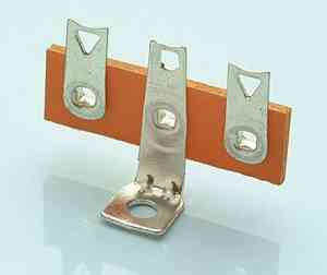
These tag strips are great for point-to-point wiring. Keep in mind the middle terminal will be grounded to the chassis unless you isolate the strip from the chassis and bolt. If you plan to use the middle terminal as a ground be sure and clean the chassis around the bolt and use a star washer between the chassis and tag strip for a good chassis ground connection.
If you like this amp but would like a little more gain check out the JCM800 Micro.
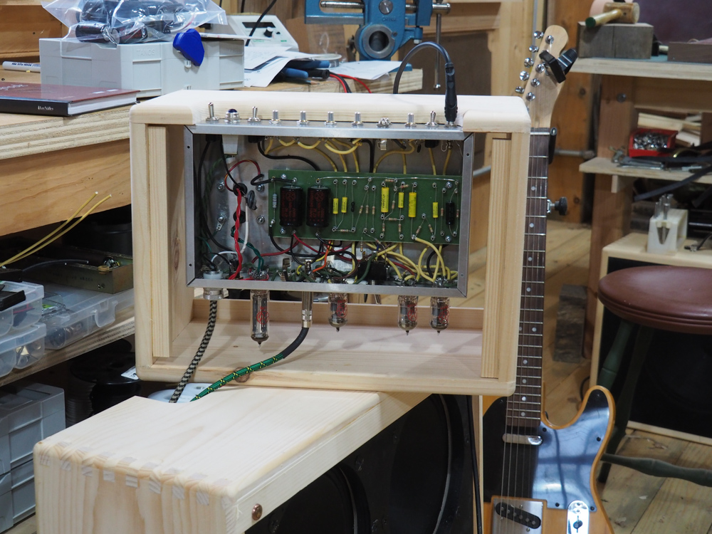
Building the Bassman Micro LTP
I get most of my parts from Tubedepot.com, Hoffmanamps.com and then Mouser.com for everything else.
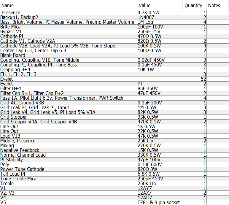
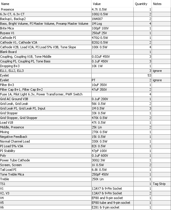
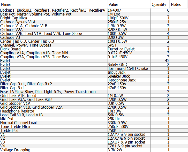
Bassman Micro LTP Bill of Materials
You'll also need a chassis, cab, speaker, power cord, wire, power and output transformers and choke.
Circuit Board by Doug Hoffman
Doug will build a Bassman Micro circuit board.
Rough estimate of total cost of the built chassis is about $285.
This is the general build sequence I recommend:
Start with the circuit board, either eyelet, turret, B9A development board or even perfboard. The circuit board should be at least 8 1/2" x 2 7/8" by 1/8" thick. Use #3 Eyelets or Turrets for 1/8" (0.125") thick board.
I like to measure and record the resistance value for all the resistors as I put them on the circuit board. Knowing the exact resistance value can come in handy when measuring bias and troubleshooting and it can keep you from putting a 470 ohm resistor where a 470K is called for.
Install the rest of the components to populate the board but don't start soldering until they are all in place and you're sure they are placed correctly. Make sure the negative terminals of the big electrolytic filter capacitors are connected to ground because they may explode and damage the output transformer if installed backwards. Most filter caps have an 'indention' on their positive end and arrows pointing to the negative end. Remember to leave the turret top holes available for leads that run from the turret to the tubes, controls and jacks. I use the '3/4 lead wrap around the turret' method which is old mil spec. Install tube, jack and control wires to the circuit board and leave a couple inches of extra wire so you can trim to fit later.
22 gauge wire is fine for all the amp's wiring including the heater wires. I recommend you connect the 6.3V filament heater wires from the power transformer directly to the rectifier diodes or tube, then split two wires from there: a set of wires to the pilot light and one to V3 then on to V2 and V1. For wire color I like to use yellow for the signal path, red for power, black for ground and cathodes and green for heaters. This is a good time to post a pic of the board (front and back) on a guitar forum for others to review. I like the TDPRI Shock Brothers DIY Amps forum (I'm robrob). Be sure and keep a photo of the back side of the board so you can review it in case you have to troubleshoot the amp at startup--you don't want to have to remove the circuit board to verify its backside wiring and solder joints.
You need a good quality soldering iron with a clean, pre-tinned tip to successfully solder eyelets and turrets. Frequent tip steam cleanings using a damp sponge will keep your solder joints looking good. When soldering eyelets I like to use a little flux paste on the eyelet and the component leads because it really helps the solder adhere for a good, long term connection. I just dab a little on the joint using a thin artist paint brush. Chasing a cold solder joint can be a colossal pain in the butt.
When soldering turrets keep in mind they are pretty good heat sinks so you need to apply soldering iron heat to the turret for a few seconds before making contact with the component leads. This will keep you from frying components as you wait for the turret to get hot enough to bond with the solder. Speaking of frying components, it's a good idea to use a heat sink clamp on component leads--especially capacitor leads--to protect the component. Even just an alligator clip on the component lead between the soldering iron and component body will protect it from over heating.
I used a spare Marshall 18 Watt chassis for my build. It's designed for 9-pin EL84 power tubes so there's plenty of small 9-pin tube socket holes available. It's also easy to find or build an 18 Watt cab. The 5E3 Deluxe chassis may work to fit the 8 1/2" x 2 7/8" circuit board. You will need 1 or 2 (2 for tube rectifier) octal-to-noval (8-pin to 9-pin) hole adapters so you can fit 1 or 2 tubes where the 6V6 power tubes would go. You will also have some extra input jack holes but you can use these holes to mount switches for things like switched negative feedback and the bright switch. You can always use a normal, 8 pin sized 5Y3GT as the rectifier tube since that size hole is already available. This is probably the easiest way to go because there are so many 5E3 combo cabs and head cabinets available. You can also go with a 'table top' style chassis that could easily be installed in a small cab. The Hammond 1444-1273 12 x 7 x 3" blank chassis is perfect but you will have to drill your own jack, pot and tube holes using a step drill bit.
Bassman Micro EF80 Voltage Chart

Mount the tube sockets, pots, fuse, power switch, pilot light and transformers in the chassis and do as much wiring on these as you can before you mount the circuit board because it will get crowded in the chassis. Don't forget to do the heater wires first, before you install the circuit board and begin hooking up the other tube leads. Try to keep the tightly twisted heater wires down against the chassis floor to reduce noise and hum.
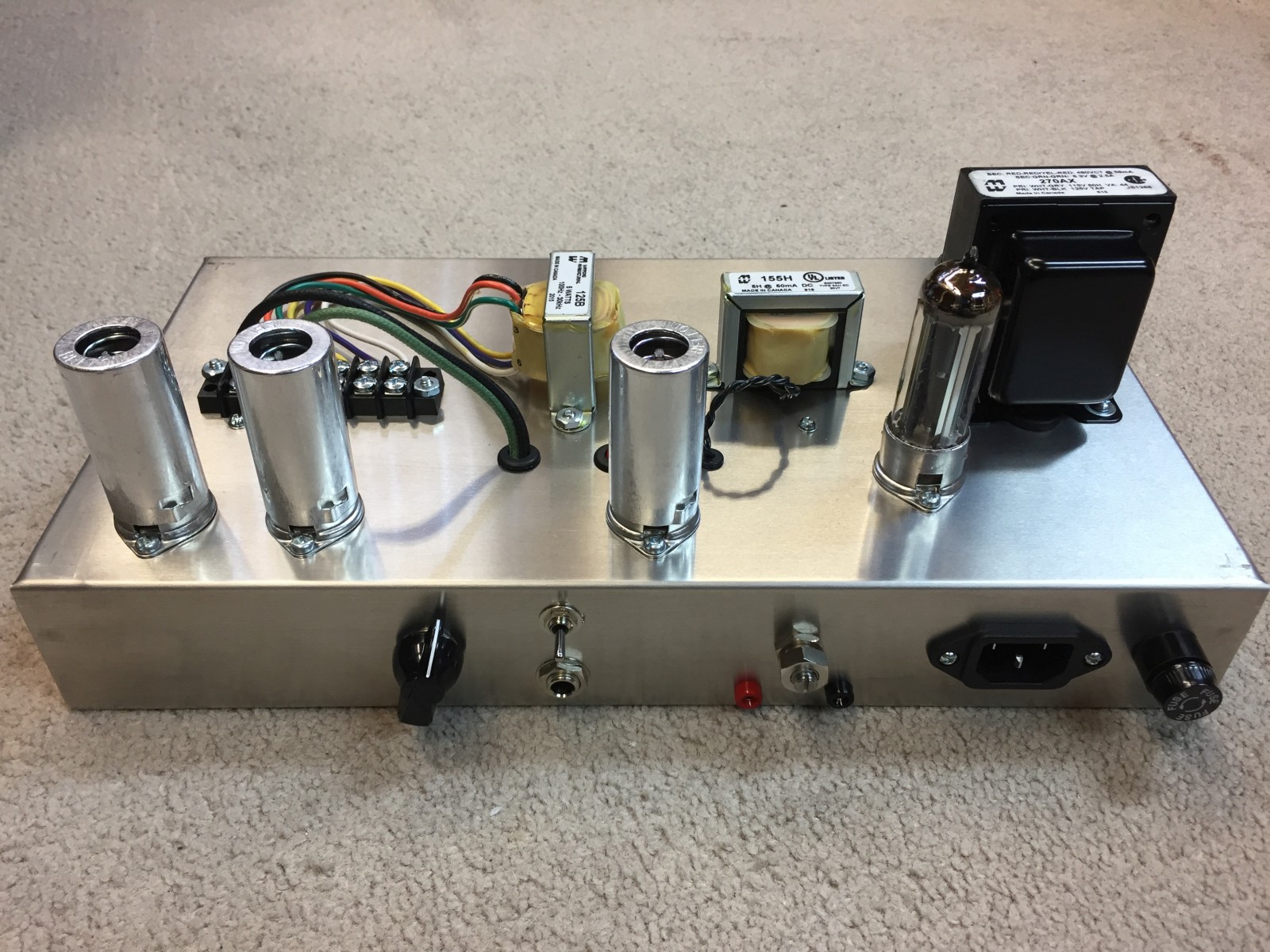
Hammond 270AX Power Transformer
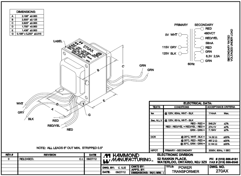
Most of us in the U.S. will want to use the 125V primary tap so the White and Black wires would be used (heat shrink the unused Gray wire). The transformer's Black wire connects to the power cord's Hot-black-narrow prong wire. The White wire connects to the power cord's Neutral-white-wide prong wire. Connect the power cord's green safety ground wire to a transformer mounting bolt. For output power to the rectifier use the two Red wires for 240-0-240V of high voltage. The Red/Yellow center tap wire connects to the negative terminal of the B+1 Filter Capacitor. The two green 6.3V wires go to the pilot light and all tube heaters. Note the EZ81 rectifier tube has non-standard heater pin numbers.
240 Volt Primary Wiring for Hammond 370AX
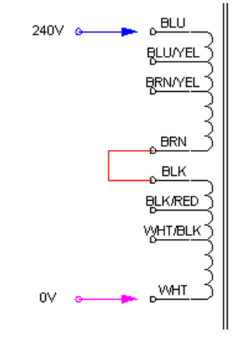
International builders should use the Hammond 370AX with 100, 110, 120, 200, 220 and 240v primaries. Don't forget to connect the Brown and Black wires together.
Power Cord Wiring
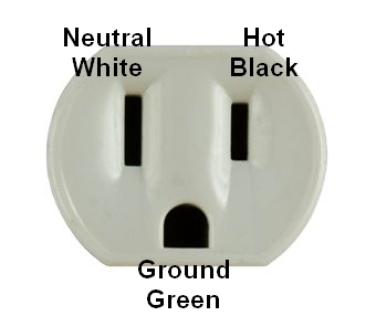

Modern U.S. wall cords and sockets have a narrow blade for Hot (black wire 120v), a wide blade for Neutral (white wire ground), and a round or 'D' shaped prong for the chassis Safety Ground (green wire ground--the Neutral and Safety Ground are connected at the main circuit breaker box). Power cord wire colors are sometimes non-standard so use a multimeter to identify Hot and Neutral.
Install the circuit board and connect all the leads. Post detailed pics for forum review before applying power. I recommend you follow my Amp Startup Procedure. Following it can prevent damage from a miss-wired amp. If you have a light bulb current limiter you should use it for the startup.
David Jones' Bassman Micro Chassis
David chose to use a 5Y3 rectifier tube and Hammond 270CAX power transformer. Photo by David Jones.
Steven Hebb's Bassman Micro
Photos and amp build by Steven Hebb
Kevin Barlow's Bassman Micro
Build and photos by Kevin Barlow. Kevin added my Tube/Solid State rectification switch 5F6A mod. See more of Kevin's photos here.
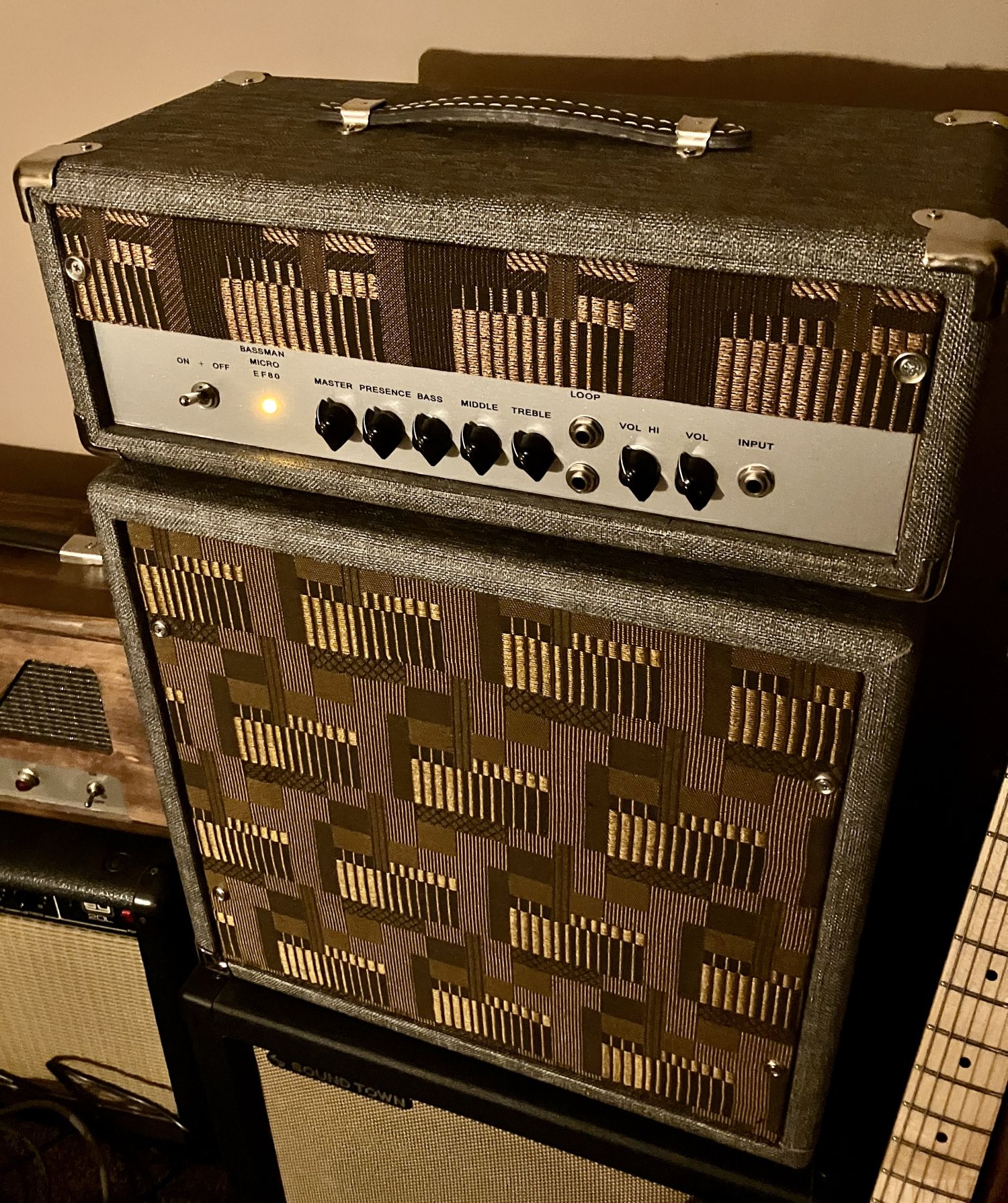
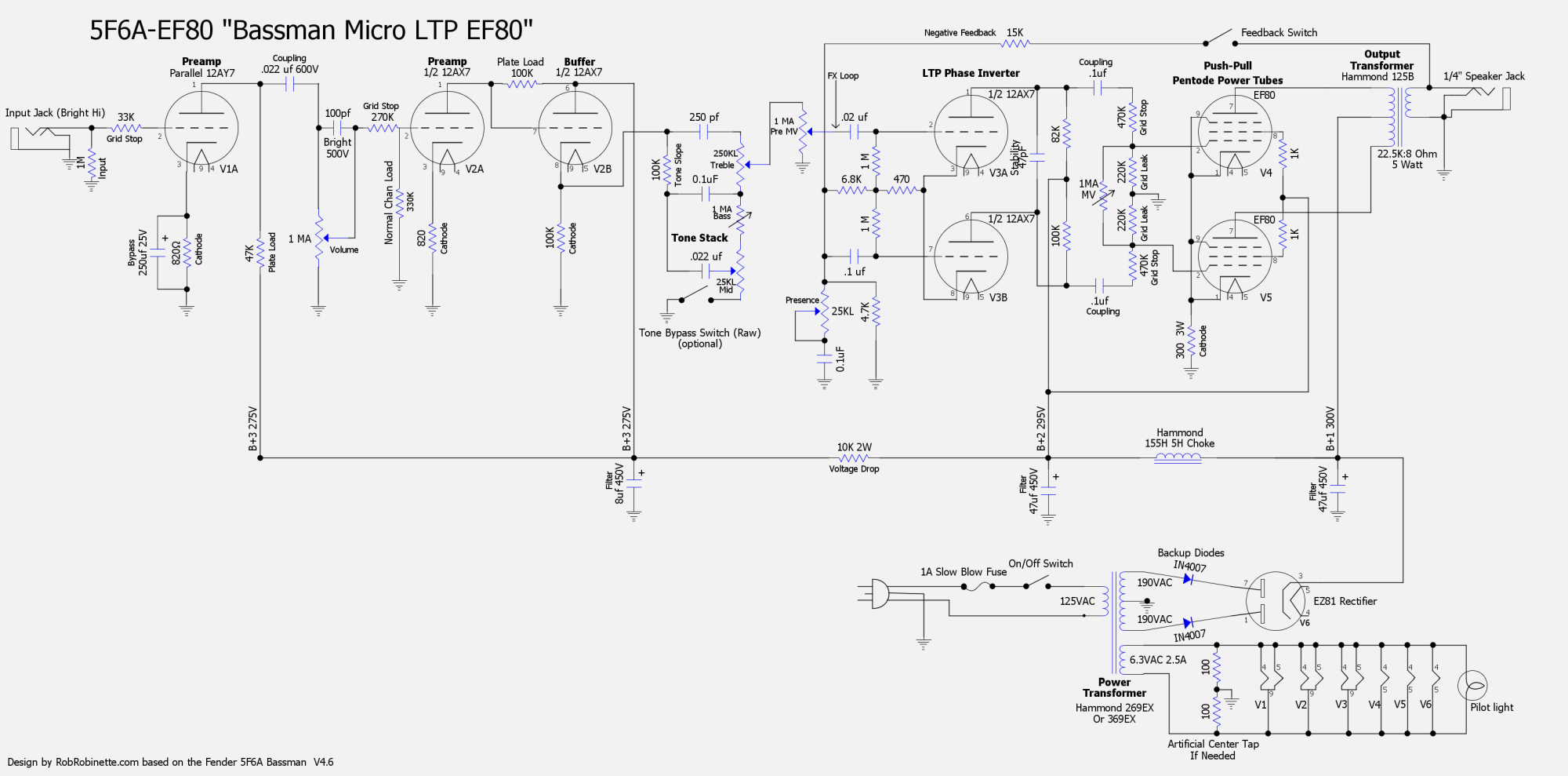
Bassman Micro LTP EF80
This version of the Bassman Micro LTP uses two EF80 novel pentodes in push-pull for true pentode power tube overdrive with about 4 watts of output power. Pentodes overdrive differently than triodes due to their screen grid so this is a way to get pentode overdrive in a 2 watt power amp. The power amp shown below can be adapted to pretty much any preamp, including high gain amps like the Soldano SLO-100 and 50. For best results keep the plate voltage between 220 to 300 volts (design max is 300v for plate and screen).
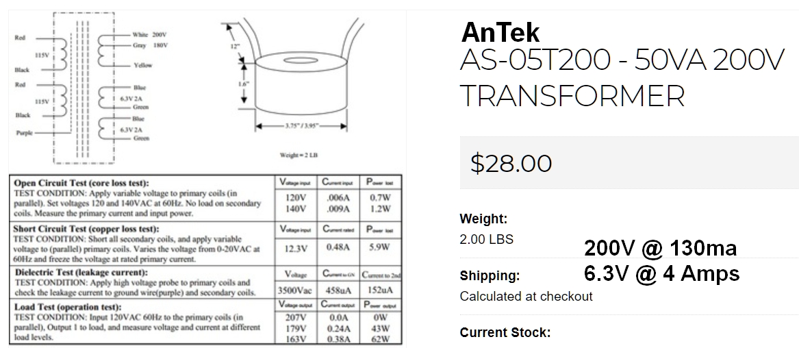
The layout below shows an EZ81 tube rectifier with an $89 Hammond 269EX 190-0-190V power transformer with 190-0-190 high voltage at 75ma, 2.5 amps of 6.3v heater current. For international builders I recommend the Hammond 369EX (or the AnTek in the next paragraph) which has 100, 110, 120, 200, 220,230, 240 VAC 50/60 Hz primaries. The 269EX/369EX is a good choice for any amp using an EF80 power amp but it does not include a 5v secondary so use an EZ81 (6.3v) tube rectifier or a solid state rectifier. International builders can also use the AnTek transformer described in the next paragraph. It has both 120 and 240v primaries.
My recommended power transformer is the $28 AnTek AS-05T200 toroidal power transformer 200v @ 130ma (50VA), 6.3v @ 4 amps. It must be used with a bridge rectifier. You can build the bridge rectifier with two tag strips and four 1N4007 diodes or get an inexpensive bridge rectifier like this $1 three amp 1000v bridge rectifier from Mouser. The AS-05T200 has both 120v and 240v primaries. It also has an 180v tap in case you want to lower the amp voltages (use gray and yellow wires for 180v of HT). Another bonus is it only weighs 2 lbs. Size is 3.75" in diameter and 1.6" tall. You can mount the transformer on the top of the chassis and purchase a 105x45mm round transformer cover, leave it exposed or mount it inside the chassis. Mounting consists of drilling a single hole for the transformer central bolt.
![]()
Detailed AnTek Wiring
![]()
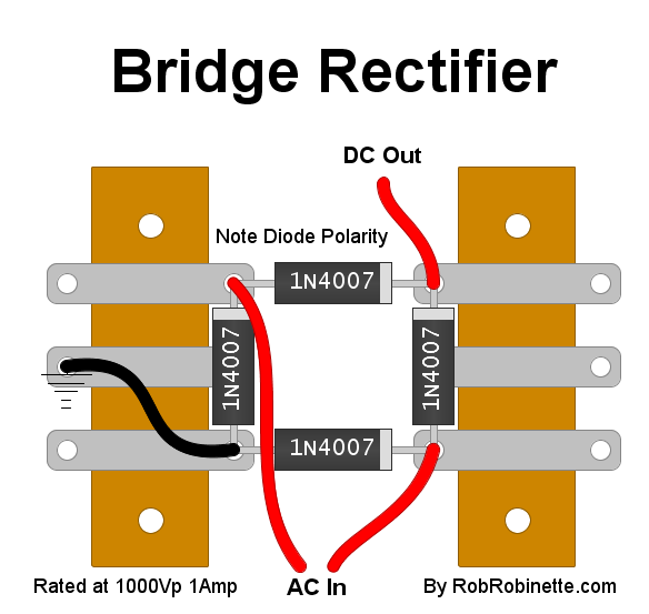
Simple to build 1000 peak volt bridge rectifier using two tag strips and four 1N4007 diodes (about 30 cents each).
New Old Stock EF80s (also called 6BX6) are inexpensive ($6) and plentiful but tend to be microphonic so they are best used in head amps and not combo cabs. So far I haven't had any combo amp builders complain of microphonics. Using rubber insulated sockets and silicone damping rings on the tubes can help with microphonics this doesn't seem to be necessary. The EF80 uses standard 9-pin sockets and 6.3v heaters so they are easy to implement into a modern amp build.
At 270 to 300v on the plates and a 300 ohm cathode resistor (as in the layout below) you can expect about 5.2v across the cathode resistor with the EF80s running at 2.45 watts, 95% plate dissipation with 8.4 milliamps of plate current per tube. Adding a 1k 1/2 watt screen resistor will add some screen sag distortion and emphasize the difference between triode and pentode overdrive.
The EF80 can also be used in the preamp like the EF86 in many early tube amplifiers.
If you like this amp but would like a little more gain check out the JCM800 Micro EF80.
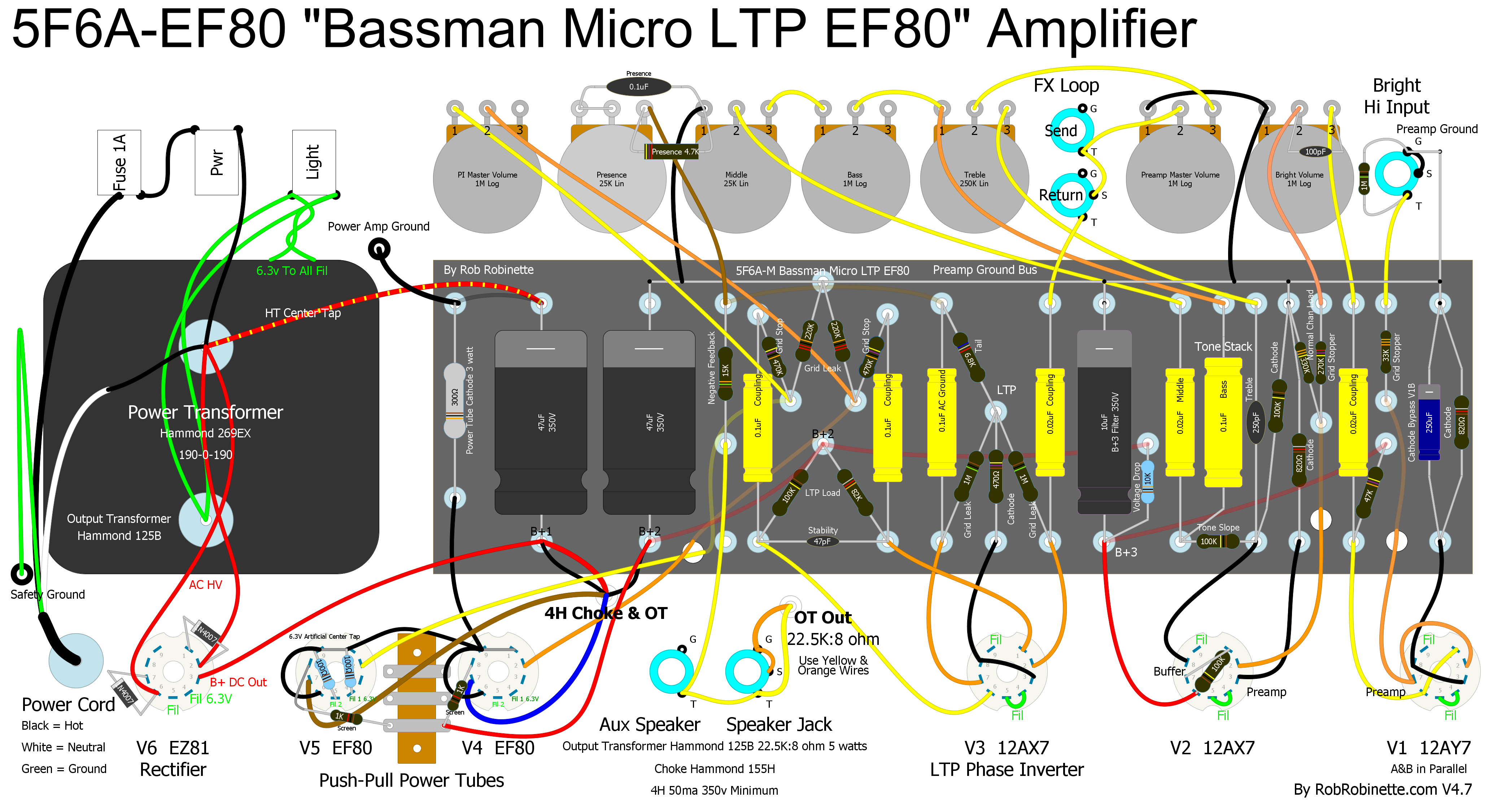
V4 & V5 are EF80 nine-pin pentodes in true push-pull fed by an LTP phase inverter for 1 watt of output. EF80 socket pins 1 (cathode), 9 (suppressor grid) and 6 (internal shield) are tied together. B+2 is connected to screen resistors and pin 8 (screen). A 300 ohm 3 watt cathode resistor is used. Output transformer is the Hammond 125B 22.5K:8 ohm and 5 watts. Click the image to see the high resolution layout, download the pdf, download the diylc file, download the Hoffman diylc board file.
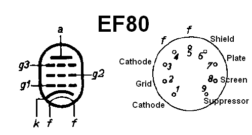
Pins 1 & 3 connect to a single cathode, pins 4 & 5 (f) are 6.3v heater filaments, pin 6 is an internal shield which is normally connected to the cathode or ground, pins 1 & 9 (cathode and suppressor grid) are normally tied together.
Hammond 125B Output Transformer Wiring & Specs
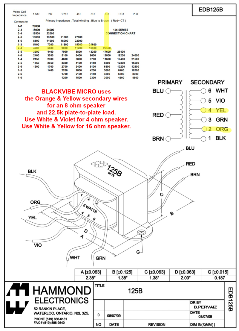
For the EF80 we want 22,500:8 ohms so we use the Yellow (4) & Orange (2) wires. We do not use the Black secondary wire.
![]()
Another (better looking) option for the output transformer is the $29 MusicalPowerSupplies.com OT5PP 22.5K:4-8-16 ohms.
![]()
Build your own push-pull output transformer specs for an EF80 push-pull power amp. You can download the program that created this graphic here.
Click the image to see the high resolution layout, download the pdf, download the diylc file.
Bill of Materials
You'll also need a Hammond 125B output transformer, Hammond 155H choke, chassis, cab, speaker and power cord.
Lar-Mar/Type-2 Master Volume for the Bassman Micro

My preferred Lar-Mar/TrainwreckType-2 master volume in the Bassman Micro EF80. This master volume will work with the Bassman Micro 12AU7 too. Note the grid leak resistors have been removed from the circuit board because the MV pot replaces them. Click on the image to see the high resolution layout. Download the pdf here and the DIY Layout file here.
EF80 Characteristics Design Chart
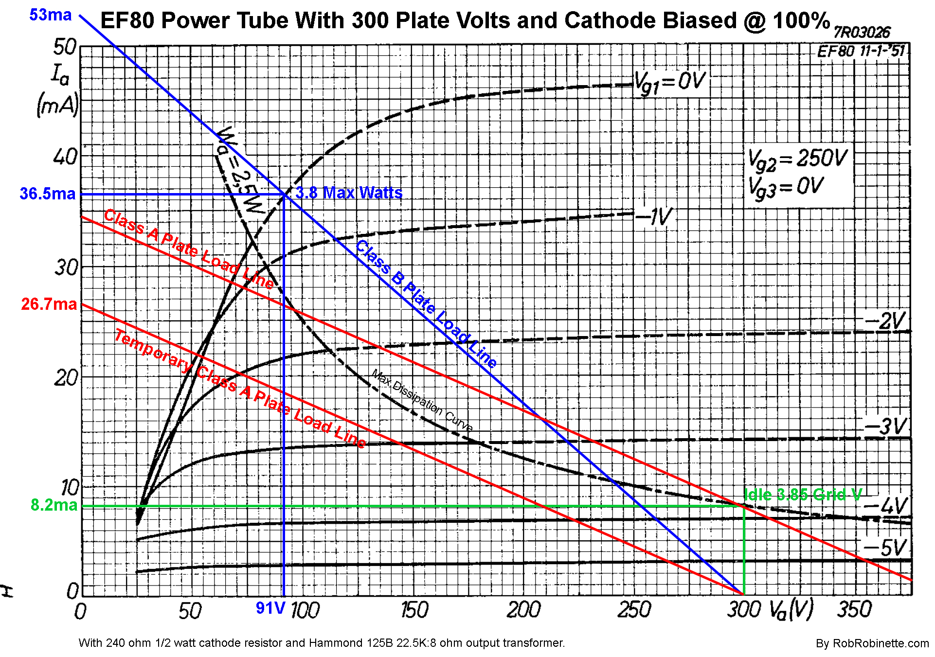
I used the characteristics chart from the EF80 datasheet to design the power amp. The green idle lines show the idle bias, quiescent or Q point. The tube will idle at 300 plate volts and 8.2ma. The lower red line is the temporary Class A plate load line which runs from 300 volts to 26.7ma. We slide the line up to meet the idle bias point so the upper red line is the actual Class A plate load line. The blue line is the Class B plate load line which runs from 300 volts to 53ma. The point where the blue Class B line intersects the 0 grid volt curve gives us maximum output power. With a voltage swing of (300V - 91V) * .0365a / 2 = 3.8 max watts at the speaker. Details of how I created this chart can be found here.
Brighten the Bassman Micro for Humbucker Guitars
Humbucker pickups pass a lot of low frequency energy to an amplifier so they tend to sound darker than single pickup guitars. The easiest mod to make a tweed amp work better with humbuckers is to reduce the size of the V1 cathode bypass cap from 25uF down to 1uF (25v or higher). This will trim some of the excess bass from the humbucker pickups which will brighten the tone. If your single pickup guitars sound too bright after the mod just roll off some highs using the guitar or the amp's tone control.
How the Bassman Micro Works
For a non-technical primer on how guitar tube amplifiers work see my How Tube Amps Work web page. If you have trouble understanding this section I suggest you go back and read this primer.
5F6A-M Bassman Micro Signal Flow
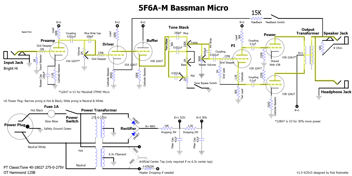
Signal flow shown in yellow highlight. The guitar signal enters at the input jack at upper left. Flows through the grid stopper resistor to the V1A (Valve 1, first half) grid for its first stage of amplification, out the plate through a coupling cap to the bright cap and volume control. The bright cap bypasses some high freqs around the volume control. The signal then goes through a 270k grid stopper to V2A's (Valve 2, first half) grid for more amplification, out the plate directly to V2B's grid. V2B acts as the Tone Stack Buffer. The signal flows out its cathode to the Tone Stack, exits via the Treble control's wiper to the Master Volume, out through a coupling cap and grid stopper resistor to the V3A Phase Inverter. The phase inverter splits the signal into two 180 degrees out of phase signals. One signal goes from the phase inverter's plate through a coupling cap to the V3A Power Tube's grid and the other signal goes out the phase inverter's cathode, through a coupling cap to the V3B power tube's grid. The signals leave V3A & B via their plates and flow through the output transformer to the speaker jack and speaker. Note: the Negative Feedback NFB circuit has been deleted from the layout but if you do choose to use NFB I recommend a change to a 15k NFB resistor.
The low voltage alternating current (AC) audio signal from the guitar's pickup coils enters the Bassman Micro at the Input Jack. Typical signal level from the guitar pickup coils is about 0.1 volt rms but can vary greatly due to the number of pickups, their design and of course how and what is played on the guitar. Soft jazz notes with a vintage single coil pickup can be in the single digit millivolt range (0.001v).
The first component the guitar signal encounters is the 1 megaohm impedance bridging Input Resistor. Impedance bridging just means the guitar's and amp's impedance match up correctly for optimum voltage signal transfer (low impedance guitar, high impedance amp). The Input Resistor also functions as the grid leak resistor for tube amplifier stage V1A (valve 1, first half of the tube). A grid leak resistor 'leaks' off unwanted DC (direct current) voltage on the tube's control grid to keep the grid at 0 volts DC. The Control Grid needs to stay at 0 volts DC to keep the tube bias correct.
After the Input Resistor the signal encounters a 33 kilo ohm Grid Stopper resistor. The Grid Stopper filters out audio signals above human hearing which helps stabilize the amplifier and prevent it from oscillating. After the Grid Stopper the signal hits Tube V1A's Control Grid, pin 2 in the schematic above (our 12AY7 preamp tube is actually two tubes in one--a twin triode--and V1A means 'Valve 1, first triode). V1A is called a triode because it has three electrodes (control grid, cathode and plate, a tube with a fourth, screen grid electrode is called a tetrode and a pentode has a fifth, suppressor grid electrode).
The Control Grid is the 'valve' or gate that controls the flow of electrons through the tube. The tube's Cathode (pin 3) is heated and boils off electrons that want to flow through the Control Grid to the positively charged Plate (pin1). When the guitar signal hits the Control Grid and goes negative it repels and blocks the free electrons inside the tube (like charges repel, opposite charges attract) and keeps them from flowing through the grid to the Plate. When the Control Grid goes positive it allows electrons to flow freely from Cathode to Plate. This is how the tube amplifies the weak guitar signal. The weak signal on the Control Grid controls a large flow of electrons through the tube.
The amplified signal leaves the tube through the Plate and encounters a Load Resistor and Coupling Capacitor. High voltage DC power used by the tube is brought in through a Load Resistor. The Load Resistor converts the amplification stage from current amplification to voltage amplification. The wire between tube pin 1 (plate) and the Load Resistor carries up to 250 volts DC. This wire carries both the AC audio signal and the high voltage DC power the tube needs. The Coupling Cap blocks the high voltage DC on the Plate but allows the AC guitar signal to pass through to the Bright Cap. The Bright Cap brightens the guitar signal by allowing high frequencies to pass around the Volume Control Potentiometer (pot), which is a variable voltage divider that bleeds the guitar signal to ground at low volume and lets the signal pass at high volume.
The signal then passes a 270k grid stopper and enters Tube V2A (valve 2, first triode) for its second stage of amplification. The amplified guitar signal exits the tube via the Plate and flows directly into tube V2B (DC coupled) which acts as the Tone Stack Buffer. The buffer keeps the tone controls from loading down the V2A preamp stage. The signal exits V2B at its cathode and flows into the Tone Stack which filters the signal using the Treble, Bass and Mid pots. The signal exits the Tone Stack and hits the Master Volume and Master Volume Brite Cap. The Brite Cap passes high freqs around the Master Volume to keep the signal from getting too dark at low Master Volume levels. The Master Volume controls the signal level that flows through a 270K ohm grid stopper resistor to Tube V2B's control grid. The large value 270K grid stopper helps prevent blocking distortion in the Phase Inverter. V2B functions as a Phase Inverter. It creates two signals that are 180 degrees out of phase with one another. These two signals then feed into the push-pull power tube V3A and V3B.
Tube V3 functions as our power tube and is a 12AU7 twin triode tube . Both triodes are used to form a push-pull power amp. This final stage of amplification creates a high voltage, low current signal which is passed to the output transformer. The Output Transformer's primary takes in a high voltage, low current signal (high impedance) and puts out a low voltage, high current signal (low impedance) through the blue wire to the speaker jack and on to the speaker. Typical Bassman Micro output is 1 to 2 watts into an 8 ohm speaker with a 12AU7 power tube and 2 to 4 watts with a 12BH7. The Speaker's Voice Coil needs high current to create the magnetic field that interacts with the Speaker Magnet to make the voice coil and Speaker Cone move in and out creating the air pressure waves our ears perceive as the sweet sound of electric guitar.
Bassman Micro with Cathodyne Phase Inverter
You save one tube using a cathodyne phase inverter versus a Long Tail Pair phase inverter.
The optional Headphone Jack can be full size 1/4" or the now more common 1/8". The nice thing about a 1/8" jack is you won't mistake it for the Speaker Jack. The Speaker Jack has a 10 ohm 3 watt Headphone Resistor across it to load the output transformer with an 8 ohm load when headphones are plugged in. The 10 ohm resistor is automatically disconnected when a speaker is connected. Be careful with the volume control when using headphones. Make sure it is at minimum volume when the amp is powered up and turn the volume knob slowly to keep from blowing out your headphones and ears. The Headphone Resistor gives the additional benefit of loading the output transformer with a 10 ohm load to prevent damage if you forget to plug in a speaker. There is a jumper on the headphone jack from Tip to Ring to send the guitar signal to the Left and Right headphone channels. If you don't want the headphone jack simply delete the jack and replace the 10 ohm headphone resistor with a wire jumper.
Bassman Micro Cathodyne Layout
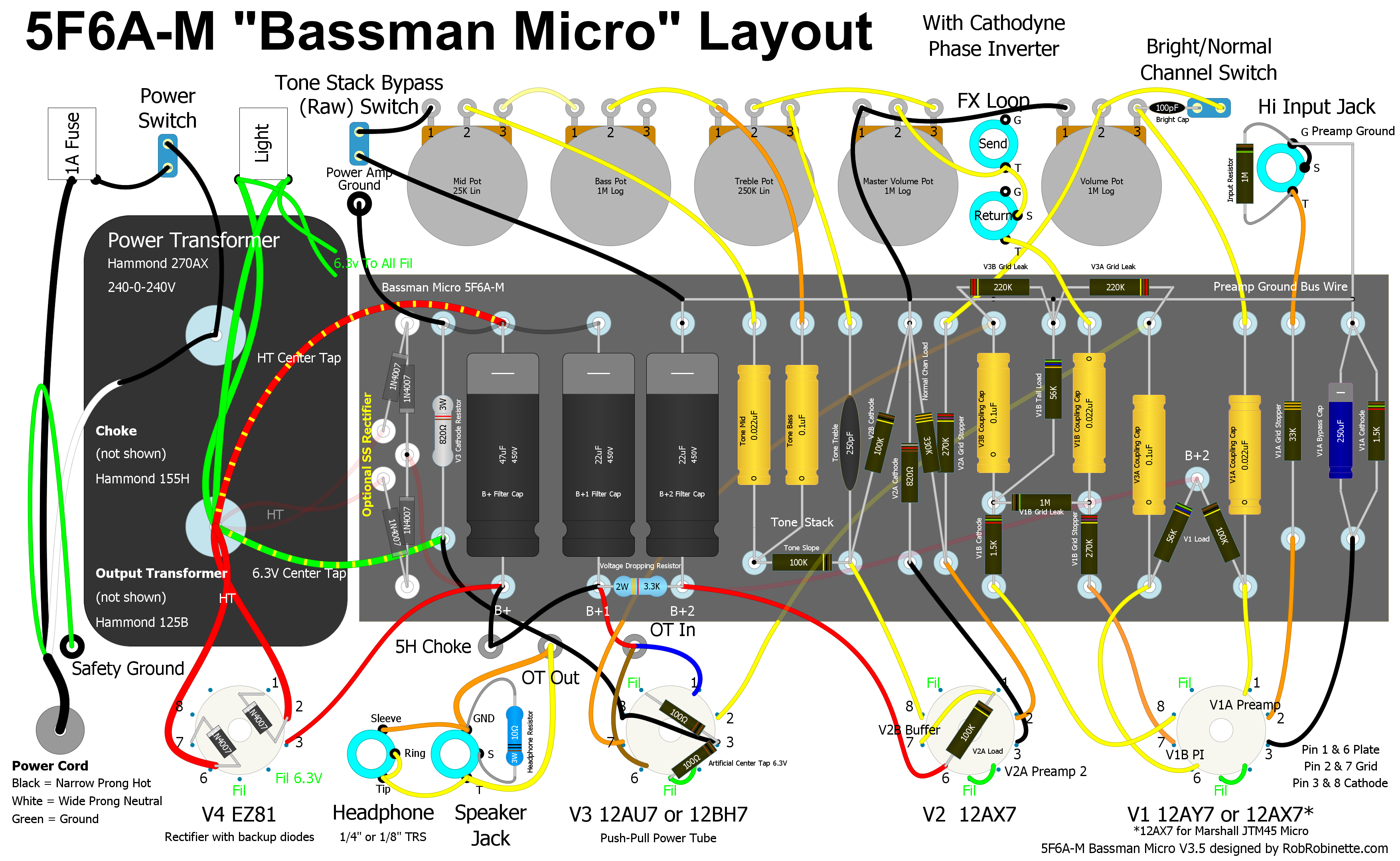
Note the optional diode rectifier is shown (left edge of circuit board) along with an EZ81 tube rectifier--choose one rectifier. Click the image to see the hi-res layout. Download the hi-res PDF layout file. Note: the Negative Feedback NFB circuit has been deleted from the layout but if you do choose to use NFB I recommend a change to a 15k NFB resistor. Click here for the DIYLC layout file.

Shown with simple four diode rectifier. Click on the image to see a hi-res pdf of the schematic (this is true of all the layout diagrams on this webpage). You can download the DIY Layout Creator file of the schematic here.
Bassman Micro Cathodyne Bill of Materials
Bassman Micro Layout For Marshall Chassis
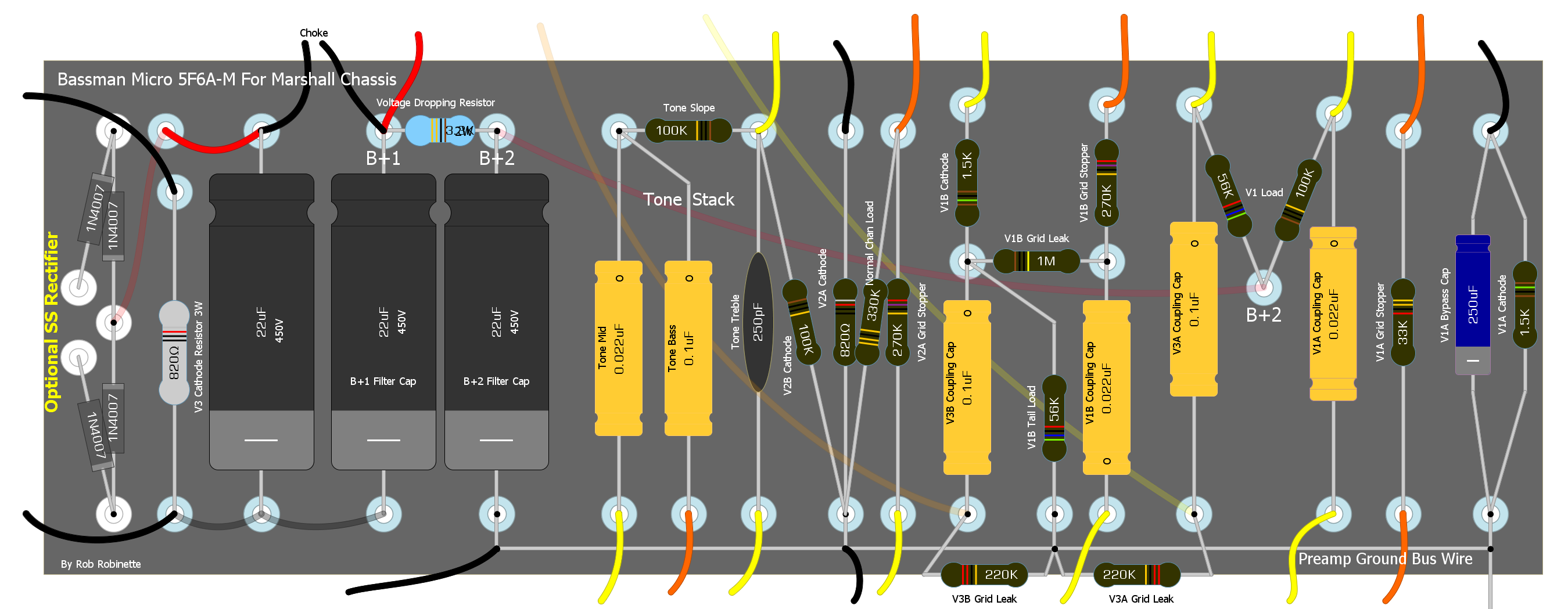
North/South has been flipped for Marshall chassis layout.
Note: the Negative Feedback (NFB) circuit has been deleted from the layout but if you do choose to use NFB I recommend using a 15k NFB resistor. See this schematic for the NFB circuit.
This undrilled JTM45 chassis will give you plenty of room and it will be easy to source a combo or head cabinet for the standard chassis size. If you don't want to drill your own chassis an 18 Watt amp chassis made for EL84 power tubes will work great since it will have five 9-pin tube holes already drilled--this is what I used. I plan to buy a combo cab and add a Weber 12" alnico speaker.
My power transformer is rated at 240-0-240 volts AC RMS but I measured 257 volts on each wire at the rectifier input due to my high wall voltage of 125.3V. Yes, that is 514 AC volts measured wire-to-wire so be careful when measuring live voltage in this amp. It's a teeny-tiny amp but it uses big amp voltage.
The Bassman Micro Cathodyne layout diagram shows both, a 4 diode solid state rectifier and an EZ81 tube rectifier--choose one and delete the other.
Measured Bassman Micro Cathodyne Voltages
Power Transformer Output 257-0-257 volts AC RMS....With 125.3V wall voltage. This is the only AC measurement, everything else is DC
B+1 304V DC...................................................................Measured at the rectifier output
B+2 299V.........................................................................Measured after the choke
Preamp V1A Plate (pin 1) 155V
V1A Cathode (pin 3) 2.05V
Phase Inverter V1B Plate (pin 6) 209V
V1B Grid (pin 7) 4 to 35V (depends on your meter's load impedance)
V1B Cathode (pin 8) 76V
Driver V2A Plate (pin 1) 154V
V2A Cathode (pin 3) 1.1V
Buffer V2B Plate (pin 6) 294V
V2A Grid (pin 7) 155V
V2B Cathode (pin 8) 162V
Push-Pull Power Tube V3A & B Plates 295V
Cathodes 9V
Bias With 295V on the plates and 9V on the cathode the plate-to-cathode voltage is 286V. I plugged those numbers into my tube bias calculator along with the 519 ohm measured cathode resistor, 1 "tubes" sharing one cathode resistor it calculated: 17.6 milliamps, 5 watts and 90.9% of max dissipation.
References
RCA Corporation, RCA Receiving Tube Manual, RC30.
Merlin Blencowe, Designing Tube Preamps for Guitar and Bass, 2nd Edition.
Merlin Blencowe, Designing High-Fidelity Tube Preamps
Morgan Jones, Valve Amplifiers, 4th Edition.
Richard Kuehnel, Circuit Analysis of a Legendary Tube Amplifier: The Fender Bassman 5F6-A, 3rd Edition.
Richard Kuehnel, Vacuum Tube Circuit Design: Guitar Amplifier Preamps, 2nd Edition.
Richard Kuehnel, Vacuum Tube Circuit Design: Guitar Amplifier Power Amps
Robert C. Megantz, Design and Construction of Tube Guitar Amplifiers
Neumann & Irving, Guitar Amplifier Overdrive, A Visual Tour It's fairly technical but it's the only book written specifically about guitar amplifier overdrive. It includes many graphs to help make the material easier to understand.
T.E. Rutt, Vacuum Tube Triode Nonlinearity as Part of The Electric Guitar Sound
[ How the 5E3 Deluxe Works ] [ Deluxe Models ] [ DRRI & 68 CDR Mods ] [ Amp Troubleshooting ] [ My 5E3 Build ] [ Spice Analysis ] [ The Trainwreck Pages ] [ Fender Input Jacks ] [ B9A Prototype Boards ]