Fender Deluxe Amplifier Evolution
By Rob Robinette
Have comments or corrections? Email rob at: robinette at comcast dot net
Fender's Deluxe amp went through many changes from 1946 to 2013, some major and some minor, but you won't find a bad sounding one in the bunch. Speaker changes among the models have more impact on tone differences than most of the circuit changes.
Model 26 Woodie Deluxe 1946-48
The first Fender Deluxe with bare wood "Woodie" cabinet, 5Y3GT rectifier tube, cathode biased 6SC7 dual triode preamp, 6N7 dual triode paraphase phase inverter, 2 cathode biased 6V6GT power tubes putting out about 14 watts.
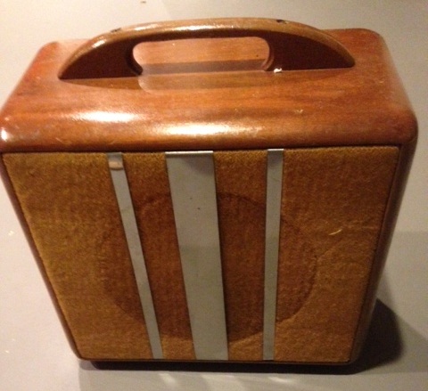
Photo by Jimmy D.
Woodie Deluxe Signal Path
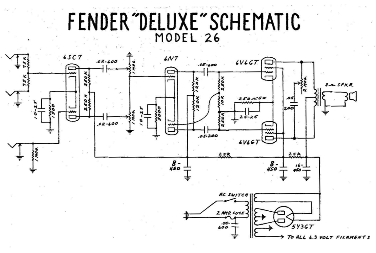
Signal path is shown with thick grey line. Note how the lower phase inverter triode's signal is tapped from the upper triode's output between the 250k and 10k voltage divider resistors.
The original Deluxe has a single cathode biased preamp stage, separate volumes for the two channels, a dual-triode paraphase phase inverter and 6V6GT power tubes. Note the three input jacks with two "Instruments" and one "Microphone" inputs, the cathode biased preamp tube and the 250k plate load resistors. The tone control is connected across the output transformer primary. The 6.3v heater filament secondary has no center tap and the circuit is unbalanced--one wire is grounded and the other is hot with 6.3v AC.
The two "Instruments" input jacks have 75k grid stopper/leak resistors. When a single input is used the two 75k resistors form a voltage divider that cuts the guitar signal in half (-6dB). This signal cut is equivalent to the later Fender "Low" inputs. The grounded side 75k resistor sets the input impedance to 75k, the other acts as a 75k grid stopper.
When both "Instruments" inputs are used simultaneously both input jack grounds are lifted so the 75k resistors no longer form a voltage divider and the channel acts like a "Hi" input. The 75k resistors do act as grid stopper and mixing resistors that help keep the two inputs from interacting with one another but neither resistor acts as a grid leak because there's no connection to ground. The guitar's volume and tone pots must function as the preamp circuit grid leak and set the amp's input impedance. The Model 26 is the only amp that suffers from this "no grid leak" issue. The single "Microphone" input jack has no grid stopper but has a 1 mega ohm grid leak resistor that sets input impedance to 1M. The result is a brighter, higher level tone roughly equivalent to a Fender standard "Hi" input.
The paraphase phase inverter acts as a full gain stage and is capable of delivering a higher voltage swing than the cathodyne and long tail pair phase inverters used in later models. The later cathodyne phase inverter has a differential gain of less than 2 and the long tail pair has about half the gain of the paraphase. The upper paraphase triode receives the input signal from the preamp tube and the lower paraphase triode taps its input signal from the upper triode's output. The paraphase upper 250k and 10k resistors form a voltage divider to drop the tapped signal to a low level suitable for the lower triode's input.
The tone control is the 2 megaohm pot and .05uF capacitor sitting between the power tube plates. It's a high pass filter that mixes high frequencies from the two outputs together. Since the two signal streams coming from the power tubes is 180 degrees out of phase mixing them together destroys the signal--wiping out high frequencies and therefore darkening the tone. This design keeps the tone control from interacting with the volume pots, a design common to all following tweed era Deluxes. Note that the pot has approximately 375v DC on it because it is connected between the power tube plates. This is not a safe design. A second cap needs to be added to the Tone pot #1 terminal (brown wire) to keep DC out of the pot. A 0.1uf 600v cap would be adequate and I also recommend upping the Tone cap to 600v.
The 6V6 power tubes have no grid stopper or screen resistors. The combination of large .05uF coupling cap, no grid stopper and large 250k grid leak resistors make severe blocking distortion (farting out) during heavy overdrive very likely. The lack of screen resistors will minimize screen voltage drop distortion caused by screen current. Screen voltage drop distortion is usually considered a desirable form of power tube distortion so minimizing it can make the power tubes sound more triode-like.
Modern Model 26 Layout
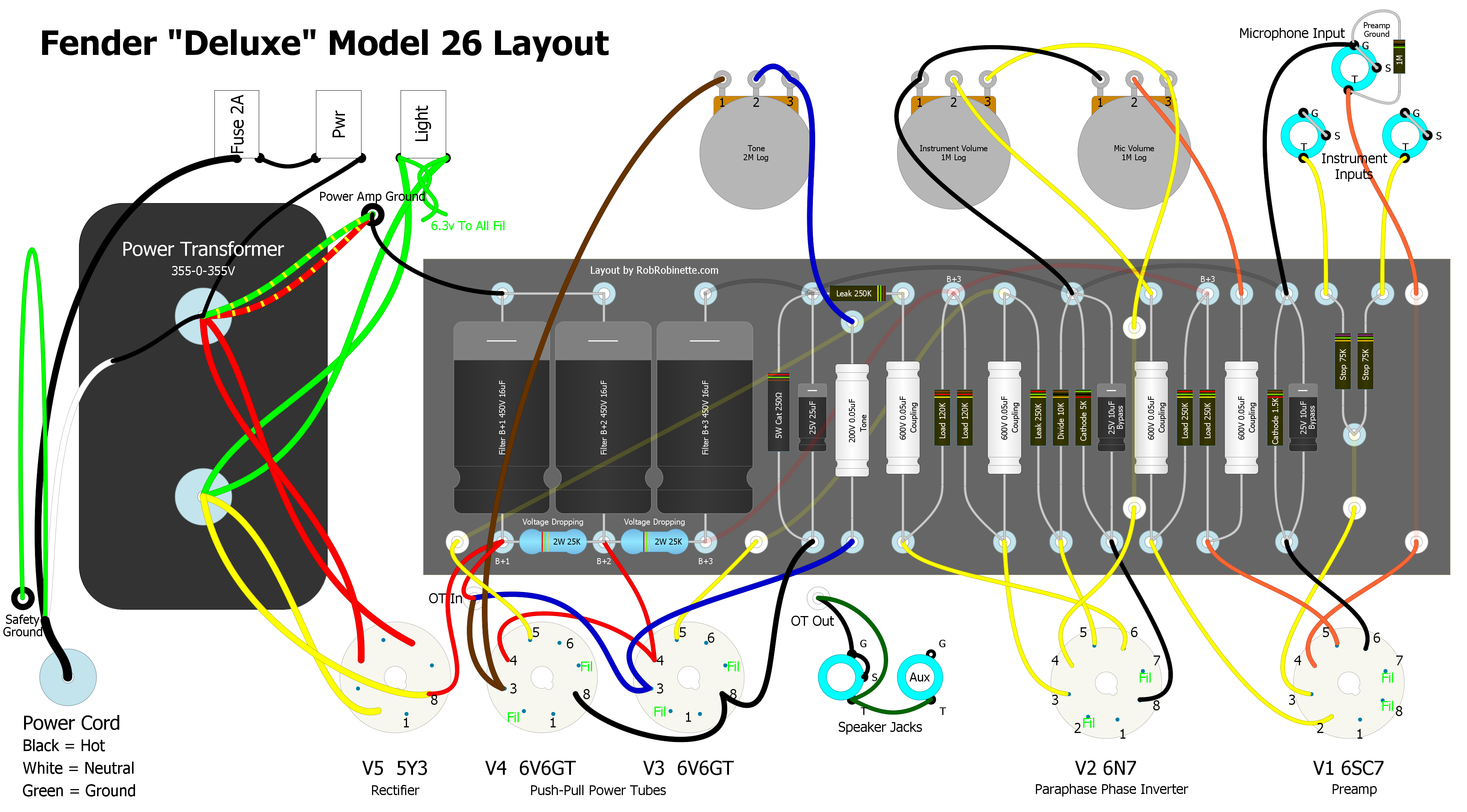
This is a Model 26 layout that follows the later tweed component placement conventions. It does not represent the actual Fender Model 26 factory layout. Click the image for the high definition image. Download the pdf here and the DIYLC file here.
Tweed Era Model Number System
The first number indicates the decade: 5 = 1950's, 6 = 1960's.
The second letter indicates the cabinet type: A & B = TV Front, C & D = Wide Panel, E & F = Narrow Panel, G = Brown, Blonde or Black Tolex.
The third number indicates the model with 3 = Deluxe.
So "5E3" = 1950's Narrow Panel Deluxe.
They are referred to as "tweed" amps because of the tweed-like fabric glued over the wooden cabinet.
5A3 TV Front Tweed Deluxe 1948-53
Grid leak biased 6SC7 preamp, 6SC7 paraphase inverter, 2 cathode biased 6V6GT power tubes putting out about 14 watts.
5A3 Deluxe Signal Path
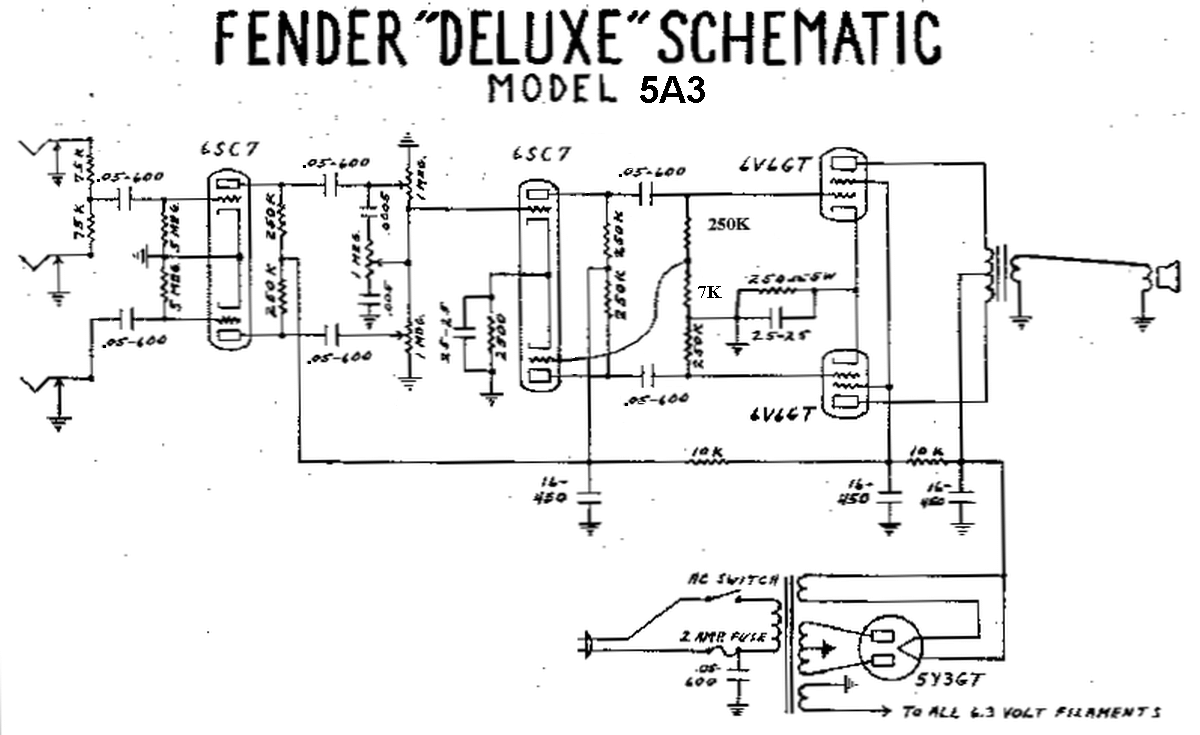
Most 5A3's came from the factory with a 100pF plate-to-plate snubber cap on the V2 phase inverter tube socket that is not shown in the above schematic. See the 5B3 Layout below to see the cap's location. Click image for clean schematic.
The preamp tube's archaic grid leak bias gets its grid bias voltage from grid current (note the grounded cathode) so input capacitors (grid leak stop caps) are required to keep the grid current from leaking out through the 75k input resistors. Since the input capacitor blocks DC current from the grid, the 75k resistors cannot function as grid leak or grid stopper resistors. The grid current is forced to flow through a large 5 mega ohm grid leak resistor causing a voltage drop that functions as the bias voltage (bias voltage is the difference between grid and cathode voltage). Grid biased amps are popular among harmonica players.
This amp's biggest weakness is that large input signals from hot guitar pickups or gain pedals can overwhelm the grid leak bias circuit and cause massive shifts in bias voltage and tube operating point. A hot signal can put the grid into positive voltage which will greatly increase grid electron flow and therefore quickly shift the tube bias. The increase in grid current charges the grid leak capacitor which adds a time-varying behavior to the circuit. If you push the amp just right so the grid bias shifts just the right amount during play you can get a very musical distortion from the preamp stage but push it too much and the bias shift can cause things to go south quickly. Another trait of grid leak biased preamps is they tend to be very sensitive to tube variations so tube swapping even among the same tube brand can lead to very noticeable tone change. This paragraph also applies to the grid biased 5B3 and 5C3 below.
Functionally the three inputs work the same as the Model 26 above except that grid leak resistors are always in circuit. The phase inverter tube is changed to a 6SC7 and the now standard tweed Deluxe interactive volume and tone controls and bright cap have been added to the two input "Instruments" (Bright upper) channel. The 500pF bright cap works by bypassing high frequencies around the volume control. The lower the volume the more is bypassed but at max volume the bright cap does nothing (at max volume there is no resistance for the Bright cap to bypass). The second and third filter capacitors are bumped up from 8uF to 16uF to reduce hum and stiffen the power supply.
The tone control moves from between the power tube plates in the preceding amps to the standard tweed position connected to the volume control which makes the two channels' volume and tone controls interact with one another. The volume control of the inactive channel and the tone control affect the active channel's gain which is a little strange but makes the tweed era amps more versatile.
The 6V6 power tubes have no grid stopper or screen resistors like the Model 26 above but the power supply rail dropping resistor between B+1 (power tube plate) and B+2 (screen) is decreased from 25k to 10k which would reduce the voltage drop between the 6V6s' plate and screen. This higher screen voltage would boost output power.
5B3 Wide Panel Tweed Deluxe 1953
The 5B3 is identical to the 5A3 but its cabinet is a wide panel design like the 5C3 below.
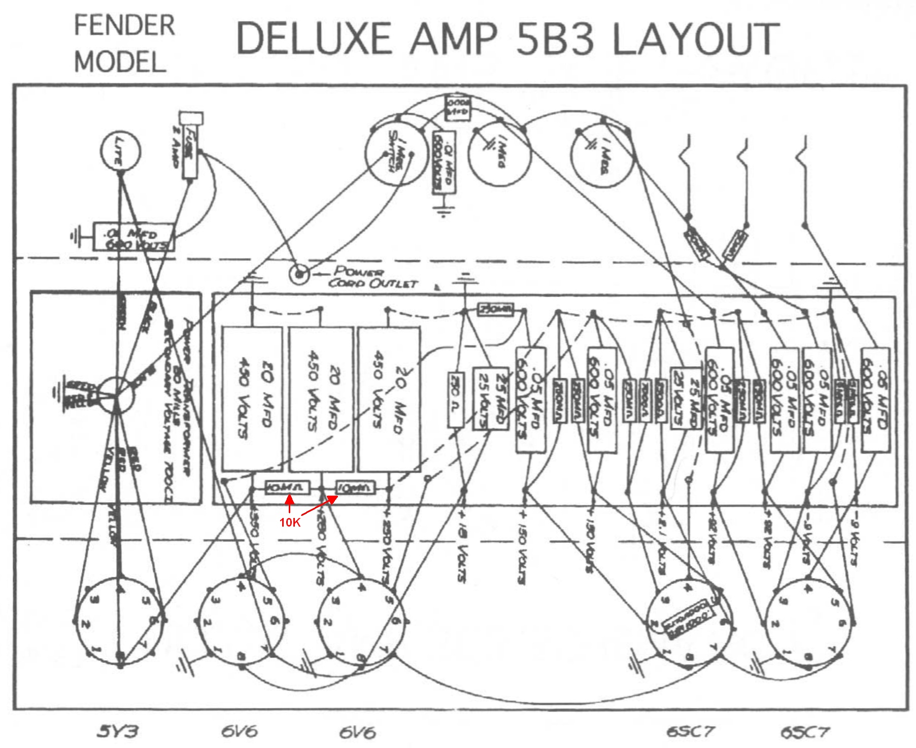
Note the 100pF plate-to-plate snubber cap on the V2 phase inverter tube socket. This cap is in place on most 5A3 Deluxe amps too. The first voltage dropping resistor is shown as 10M on this layout but both dropping resistors are actually 10k (shown in red).
5C3 Wide Panel Tweed Deluxe 1953-54
Grid leak biased 6SC7 preamp, 6SC7 paraphase inverter, Negative Feedback circuit, 2 cathode biased 6V6GT power tubes putting out about 14 watts.
5C3 Deluxe Signal Path
Click image for clean schematic.
Note the doubling of size of the input capacitors from .05uF to .1uF to extend bass frequencies, the change of paraphase resistor values to massage gain and balance, and the addition of a Negative Feedback circuit which decreases distortion and hiss, slightly decreases output and increases headroom. Negative feedback also tightens the transition from clean to dirty so picking dynamics are affected. With negative feedback the 5C3 is a more civilized amp than the 5A3 and 5B3.
Functionally the three inputs work the same as the Model 26 above except the grid leak resistors are always in circuit. See the 5A3 above for info on the 5C3's grid leak biased preamp. The 5C3's larger .1uF input (grid leak stop capacitors just after the input jacks) will slow the time-varying behavior of the grid bias circuit.
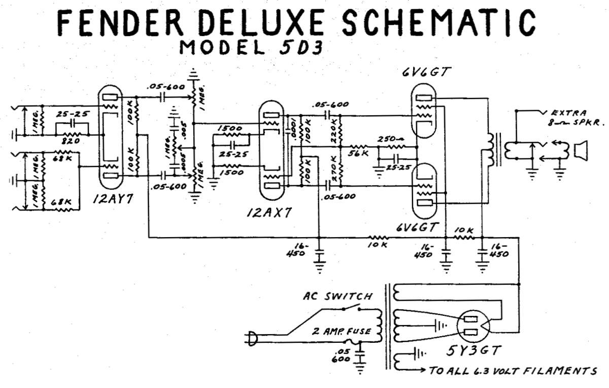
5D3 Wide Panel Tweed Deluxe 1954-55
Cathode biased 12AY7 preamp, 12AX7 paraphase inverter, Negative Feedback circuit removed, 2 cathode biased 6V6GT power tubes putting out about 14 watts.
5D3 Deluxe Signal Path
Click image for clean schematic.
Note the change to a "normal" cathode biased 12AY7 preamp. The preamp and phase inverter plate load resistors are dropped from 250k to the now standard 100k. The paraphase inverter is changed to a 12AX7 with separate cathode resistors and only the upper triode bypassed and reconfigured paraphase resistors--all of this to adjust gain and balance. A .0001uF stability cap is added across the phase inverter plates to prevent oscillation. The deletion of the negative feedback circuit will cause earlier onset of overdrive distortion (less headroom). Amps with no negative feedback tend to have a "lazy," wide transition from clean to distortion.
The input circuit is revised. The single "Microphone" input is still a "Hi" input with no grid stopper resistor and the dual "Instrument" inputs are "Low" because its two 68k grid stopper/leak resistors form a voltage divider and dump half the signal to ground. But when both "Instrument" inputs are used simultaneously they both function as "Hi" inputs because both jack's ground connections are lifted so no voltage divider is formed.
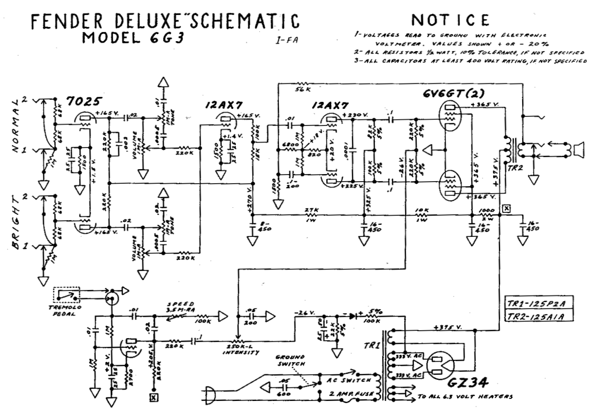
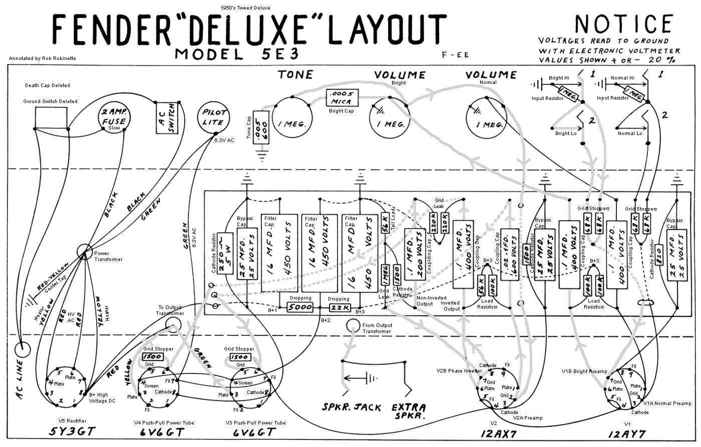
5E3 Narrow Panel Tweed Deluxe 1955-60
12AY7 preamp, additional 12AX7 gain stage, 12AX7 cathodyne phase inverter, 2 cathode biased 6V6GT power tubes putting out about 14 watts.
5E3 Deluxe Signal Path
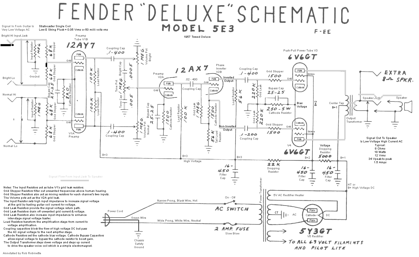
Click the image for the full size readable annotated image.
Considered "The" tweed Deluxe, the 5E3 was by far the most popular tweed amplifier. Note the now standard Fender four input (Bright-Normal, Hi-Low) circuit. Note the only difference between the two input channels is the 500pF bright cap which bypasses high freqs around the Bright volume pot. The very large .1uF coupling caps extend bass frequencies and lead to the 5E3's famous full tone and infamous loose low end. A second preamp gain stage is added with both stages fully bypassed with 25uF bypass caps to increase gain. This increased preamp gain leads to much more preamp distortion available at the turn of the volume dial which suited a new form of music called Rock and Roll.
The phase inverter is changed from paraphase to cathodyne (unique to the 5E3). The extra preamp gain stage makes up for some of the gain lost in the phase inverter but the low gain cathodyne phase inverter simply cannot drive the power tubes as hard as a paraphase or long tail pair phase inverter so the 5E3 offers less power tube distortion than some other Deluxe amps. The main advantage of the cathodyne phase inverter is not sonic, but cost and simplicity as it only requires 1/2 of a 12AX7. The cathodyne phase inverter's dual signal output is extracted at the plate (inverted signal) and at the cathode (non-inverted signal). Each signal stream feeds a power tube.
The 5E3 Deluxe Layout
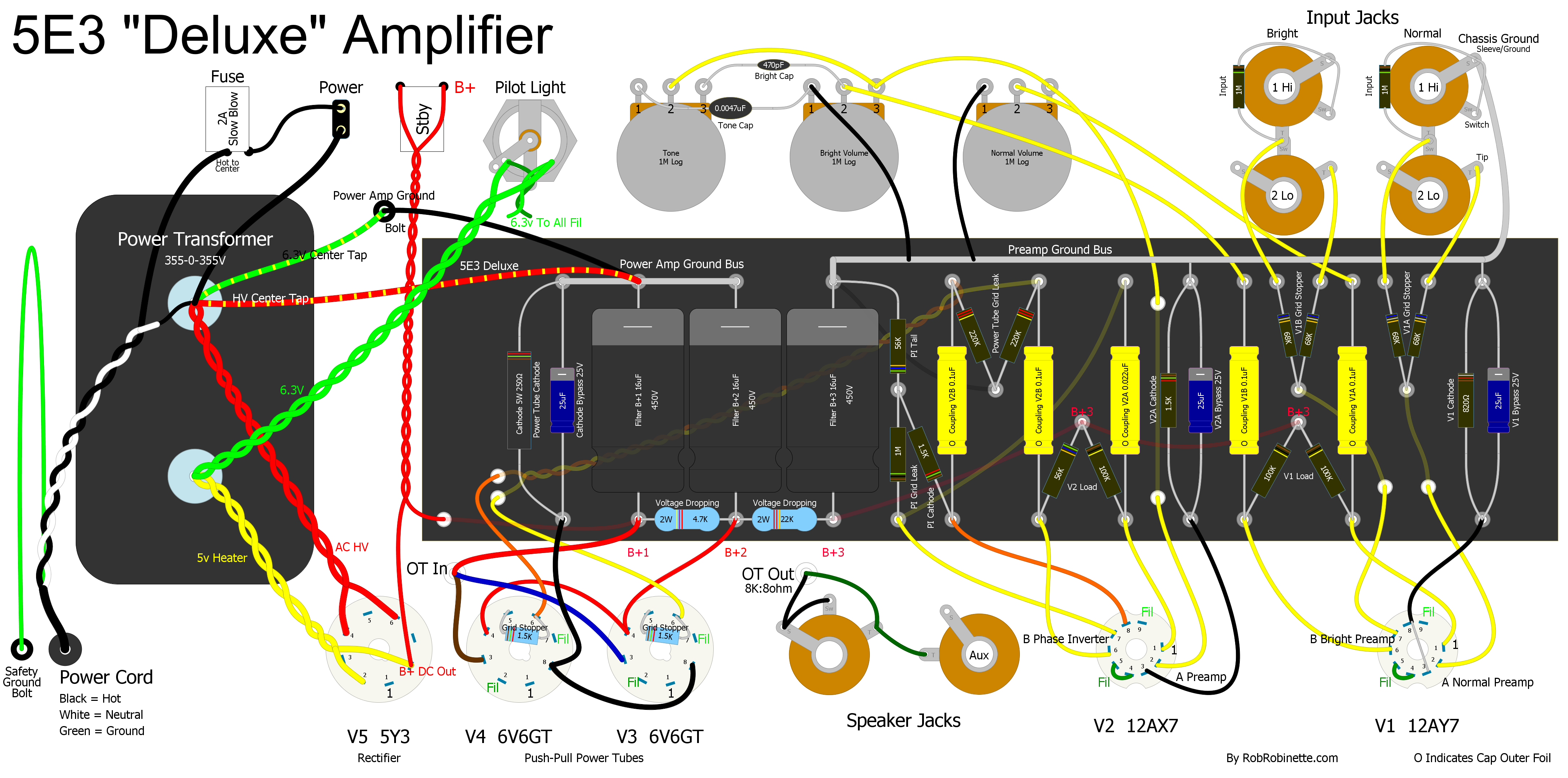
Click the image to view the full size layout diagram. Click here to download the DIYLC file so you can modify this layout diagram yourself. A split power amp/preamp ground bus design is used.
The voltage dropping resistors are changed from 10k + 10k to 5k + 22k. The drop from 10k to 5k would raise screen (B+2) voltage which would increase power output. Going from 10k to 22k for the second dropping resistor would lower preamp (B+3) voltage which would slightly reduce gain and put less stress on the preamp and phase inverter tubes.
1.5k power tube grid stopper resistors are added in an attempt to control blocking distortion and "farting out," but the power tubes' coupling cap was doubled in size from .05uF to .1uF. The larger cap was used to enhance bass response but it also increased overdrive grid bias voltage shift and shift recovery time which causes the 5E3's tendency to "fart out" with severe blocking distortion.
The amp's signal path is shown on the above schematic in thick grey and component functions are listed. See the annotated 5E3 layout with signal path here. See my How the 5E3 Deluxe Works , 5E3 Modifications and My 5E3 Build web pages for more info. Download the Duncan Power Supply Designer II and the 5E3 power supply file. The 5E3 is a simple but great sounding amp and makes an excellent first tube amp build kit.
6G3 Brownface Deluxe 1961-63
Bias wiggle single triode tremolo, 7025 (premium 12AX7) preamp, 12AX7 long tail pair phase inverter, Negative Feedback, GZ34 rectifier, 2 6V6GT power tubes using non-adjustable fixed bias putting out about 20 watts. The amp is called "brown face" due to its control panel color.
6G3 Brown Face Deluxe Signal Path
Tremolo circuit at bottom left. Note both channels have a 500pF "bright cap" across the volume control but the Bright channel's tone cap is twice the Normal channel's size at .02uF. The Normal channel also has a .002uF plate load resistor bypass cap which darkens the Normal channel's tone. Click image for clean schematic.
The 6G3 marks a big break from the previous Deluxe designs. The separated tone and volume controls with the addition of 220k mixing resistors remove most of the control interaction the previous 5E3 is famous for. Input channels are officially changed to "Normal" and "Bright." The phase inverter was upgraded to a modern long tail pair which has much more voltage swing than the 5E3's no-gain cathodyne phase inverter so the long tail pair phase inverter can drive the power tubes harder and generate more power tube distortion. The long tail pair phase inverter upper triode passes the guitar signal to its lower triode through their connected cathodes. The LTP phase inverter is the most common phase inverter in guitar amps and is known for keeping its composure during overdrive and the resulting sweet overdrive tone. The first stage preamp goes from 100k to 220k plate load resistors and the cathodes share a 1.5k resistor (equivalent to 3k for each triode) for higher gain.
Note the 100k-15k voltage divider between the second gain stage and phase inverter. This divider dumps 87% of the guitar signal to ground. Replacing the divider with a 100KA pot to form a master volume would be a good mod for the 6G3.
Negative feedback was added back into the circuit for good to reduce distortion and add headroom. Moving from the 5Y3GT to GZ34 rectifier tube increased "A" or B+1 voltage to 375v which along with fixed bias increases output from 14 to 20 watts. The phase inverter gets it's own "C" or B+3 power node with higher voltage than the preamp tubes which increases headroom, voltage swing and drive. 6.3v heater filament circuit is balanced with a center tap--both wires are hot with 3.15v AC. Balanced AC on the heater lines takes advantage of twisted pair hum cancellation to reduce heater induced hum.
Bias wiggle tremolo (bottom left) is added along with non-adjustable fixed bias power tubes. Bias is non-adjustable because adjusting the bias will change the intensity of the tremolo which is the major weakness of bias wiggle tremolo. Bias wiggle creates the tremolo (volume modulation) effect by modulating the power tube bias.
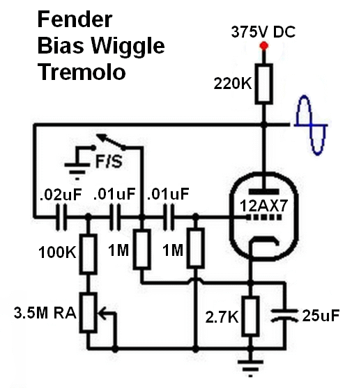
The voltage dropping resistors are changed from 5k + 22k to 1k + 10k + 27k. The drop from 5k to 1k would raise screen (B+2) voltage which would increase power output. The 10k resistor gives the phase inverter it's own, higher voltage node. The preamp's voltage drops through 38k of resistance (1k+10k+27k) which reduces (B+3) voltage which would reduce preamp gain and headroom and put less stress on the preamp tubes. Note the 12AX7 tremolo triode (V2B) is supplied with very high B+1 voltage for its plate so the V2 tube is pushed harder than the other preamp tubes and usually goes bad sooner. If the tremolo gets weak try a new V2 tube.
Power amp grid stopper resistors are removed which can lead to earlier grid current flow and grid clipping.
The 6G3 is a very cool amp that offers a tweed style tone control with black face style circuitry and makes an excellent kit build from Mojotone. The build is only slightly more complex than a 5E3 and offers up a much less idiosyncratic tone.
AB763 Blackface Deluxe 1963-66 (Non-Reverb)
Two triode light dependant resistor (LDR) preamp signal tremolo but no reverb, 7025 preamp, dual tone stacks with treble and bass controls for each channel, 12AT7 long tail pair phase inverter, 2 6V6GT power tubes using adjustable fixed bias putting out about 22 watts. The amp is called "black face" due to its control panel color.
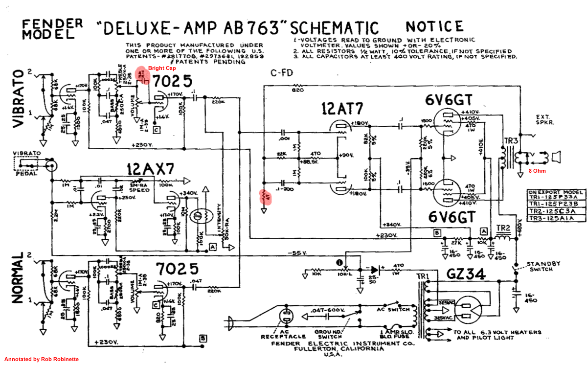
The "763" in the model name comes from the circuit change date of July 1963.
Tremolo changes from bias wiggle to preamp signal tremolo which bleeds the guitar signal to ground. Signal tremolo also allows you to bias the power tubes hot while not decreasing tremolo intensity. Note how the -55 volt bias voltage is applied to the oscillator tube's grid to keep the oscillator from functioning when the foot switch is open. A closed foot switch instantly removes the -55 volts from the oscillator grid and jump starts the oscillation.
First stage preamp plate resistors go back to 100k and each first stage triode gets it own 1.5k cathode resistor to slightly lower gain. A tone stack with treble and bass controls is added to each channel and a bright cap is used on the Vibrato volume pot. A choke replaces the 1k voltage dropping resistor between B+1 and B+2 (plates & screens) to decrease hum and stiffen the power supply. "A" or B+1 voltage is increased to 420v for punchier tone and higher output.
The long tail pair phase inverter is changed to a 12AT7 which offers less gain than the 12AX7. Phase inverter and negative feedback resistors are revised to black face standard values.
Power tube 1.5k grid stopper resistors are added again (see 5E3 above) to reduce blocking distortion and sweeten the overdrive tone. 470 ohm power tube screen resistors are added permanently to the Deluxe circuit. They drop the screen voltage to compensate for the choke's smaller voltage drop. The screen resistors also protect the power tubes during heavy overdrive from excess screen current. The screen resistors also increase screen voltage drop overdrive distortion which is a good thing.
The first filter capacitor is moved to the hot side of the standby switch to make life easier on the rectifier tube by reducing standby switch current inrush.
For more info on the AB763 amps see AB763 Model Differences.
AA763 Blackface Deluxe Reverb 1963-67
Reverb is added, Tremolo, 7025 preamp, tone stack with treble and bass controls, Vibrato channel gets a bright cap, 12AT7 long tail pair phase inverter, 2 6V6GT power tubes using adjustable fixed bias putting out about 22 watts. The Deluxe Reverb design will undergo no major changes from this point on.
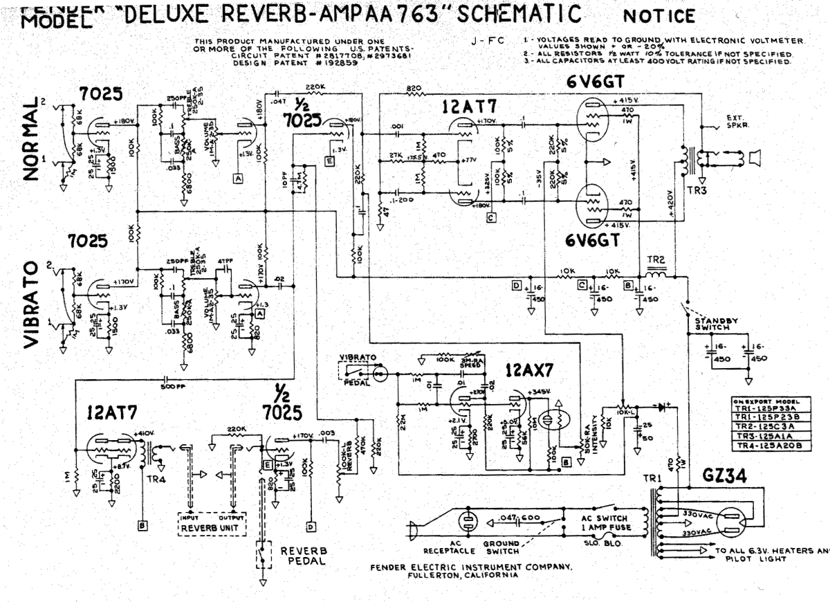
Three triode reverb is added (lower left) to the Vibrato channel along with a third gain stage to recover signal lost to the reverb circuit. A 47pF bright cap is placed across the Vibrato channel volume pot. See this explanation of how the spring reverb works. The power tube grid stopper resistors are removed inexplicably and an additional 16uF filter cap is added to the "A" or B+1 node boosting it to 32uF to reduce hum and stiffen the power supply. The power transformer secondary voltage is bumped from 325-0-325v to 330-0-330v AC but "A" or B+1 somehow stays the same on the schematic at 420v. The second voltage dropping resistor decreases from 27k to 10k to increase preamp voltage ("D" or B+4) by about 10v to increase preamp gain slightly.
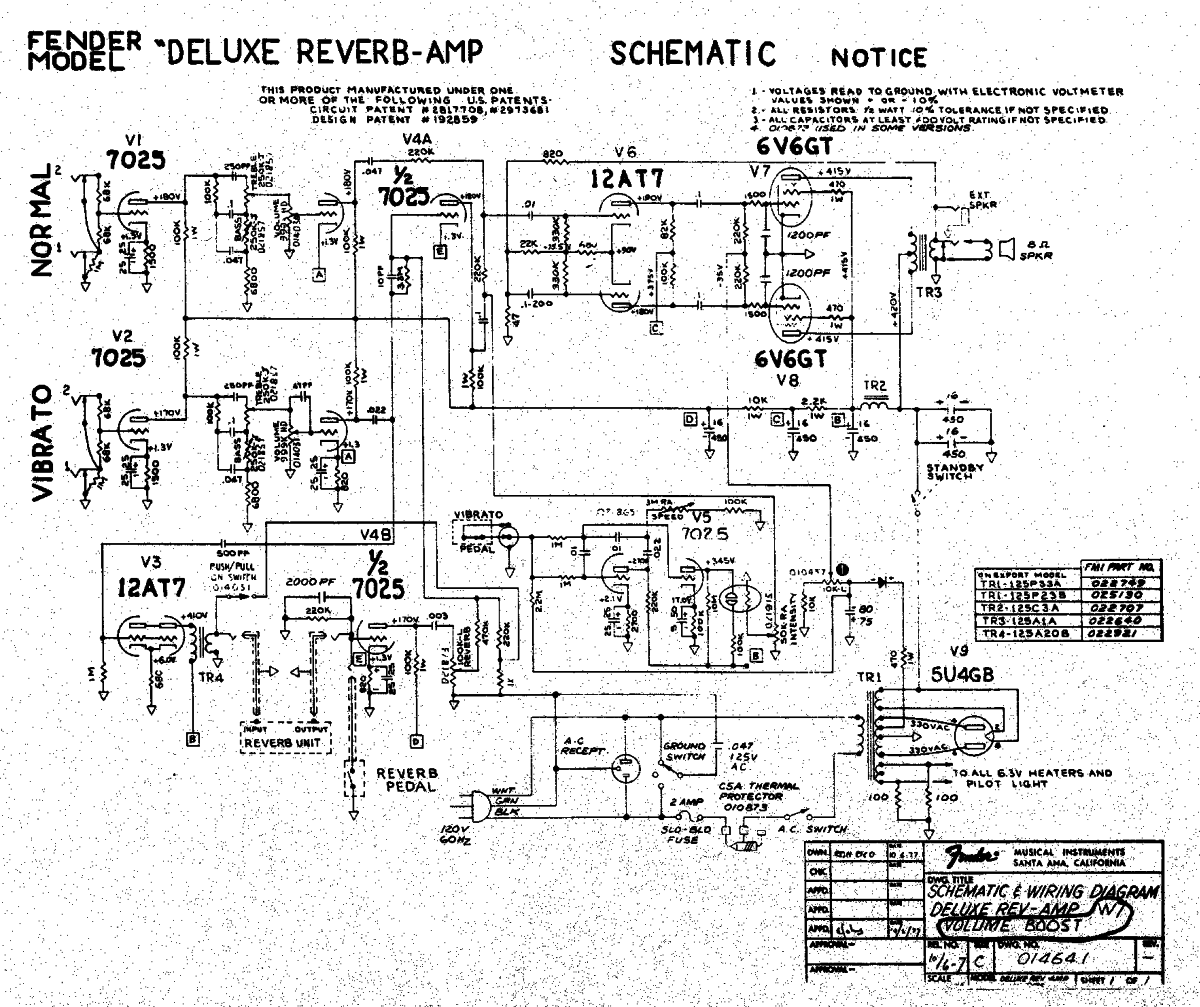
AB763 Blackface Deluxe Reverb 1963-67
This is "THE" Deluxe Reverb. The AB763 circuit is considered by most to be the pinnacle of Fender amplifier design. The circuit is the same as the AA763 above with several tweaks.
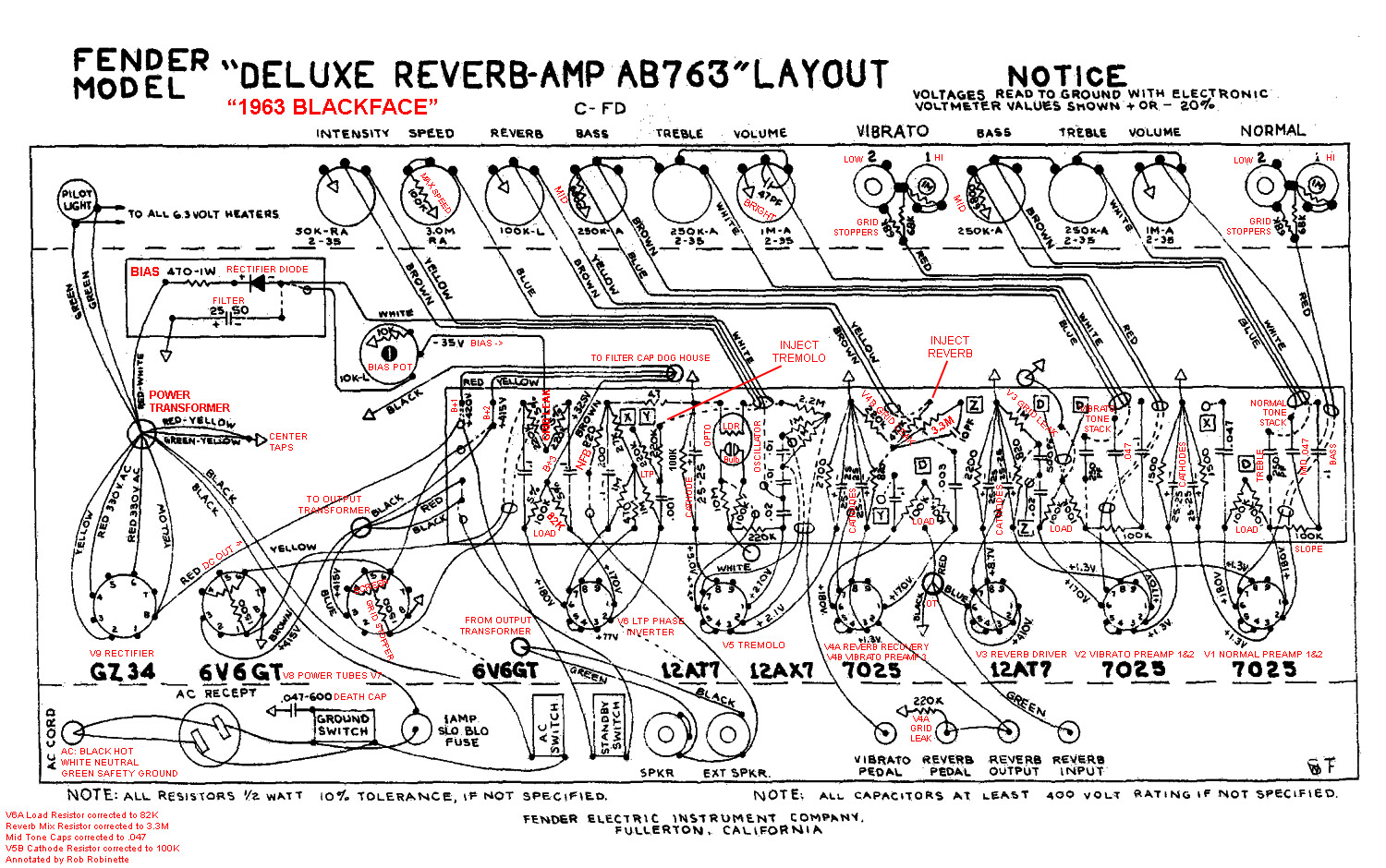
AB763 Blackface Deluxe Reverb Annotated Schematic
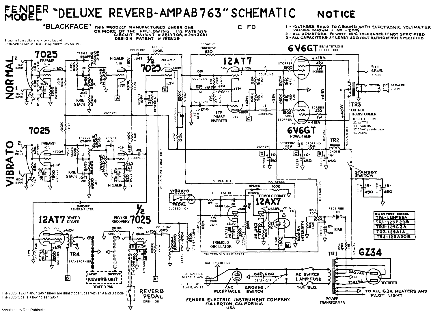
Every component's function is listed. Click image for full size, readable schematic. PDF is here.
Reverb dry signal bypass resistor drops from 4.7M to the now standard 3.3M ohms to slightly reduce the maximum reverb level. Phase inverter tail resistor drops from 27k to 22k to increase headroom but this also slightly increases phase inverter output imbalance. The phase inverter's upper plate load resistor drops from 100k to 82k to balance the inverter's output. Tone stack mid cap increases from .033uF to .047uF to pull more lows into the "mid" frequencies. The power tube grid stopper resistors are returned to help control blocking distortion and sweeten the overdrive tone. The tremolo driver cathode resistor increases from 56k to 100k. For more info see my How the AB763 Deluxe Reverb Works webpage, AB763 Modifications and AB763 Model Differences. Download the Duncan Tone Stack Calculator and AB763 tone stack file.
AB763 Signal Path

Click image for clean schematic.
Signal Flow
Click image for full size layout. PDF is here.
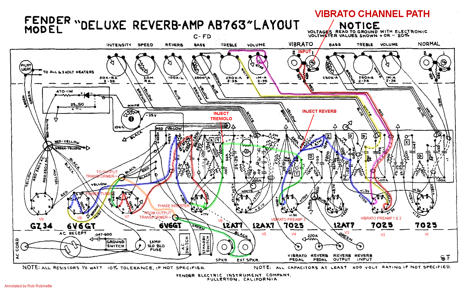
AB763 Annotated Layout
Click image for full size layout. PDF is here.
Most of the changes Fender made after the AB763 circuit made the Deluxe Reverb sound cleaner but thinner. That is why so many post-AB763 amps have been "blackfaced" back to AB763 specs.
AB868 Blackface Deluxe Reverb 1967
CBS buys Fender in 1965 and the AB868 is the first CBS Deluxe but luckily the changes from the AB763 are minimal.
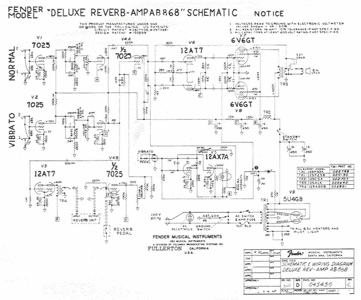
The "868" in the model name comes from the circuit change date of 8-1968.
Two 1200pF "snubber" stability caps are added to the power tube grids to prevent oscillation. Rectifier changed to 5U4GB but "A" or B+1 voltage remains the same (at least on the schematic). A 5U4GB's typical voltage drop is around 40v more than the GZ34 so the "A" or B+1 voltage should have dropped significantly from the previous AB763. Power transformer is changed to a model with no 6.3v center tap. Balanced 6.3v tube heater circuit is used with no center tap but with an artificial center tap made up of two 100 ohm 1/2 watt resistors. Bias filter cap is upgraded from 25uF 50v to 50uF 70v to decrease hum.
A1270 Silverface Deluxe Reverb 1970-77
Same as the A1172 above with minor tweaks.
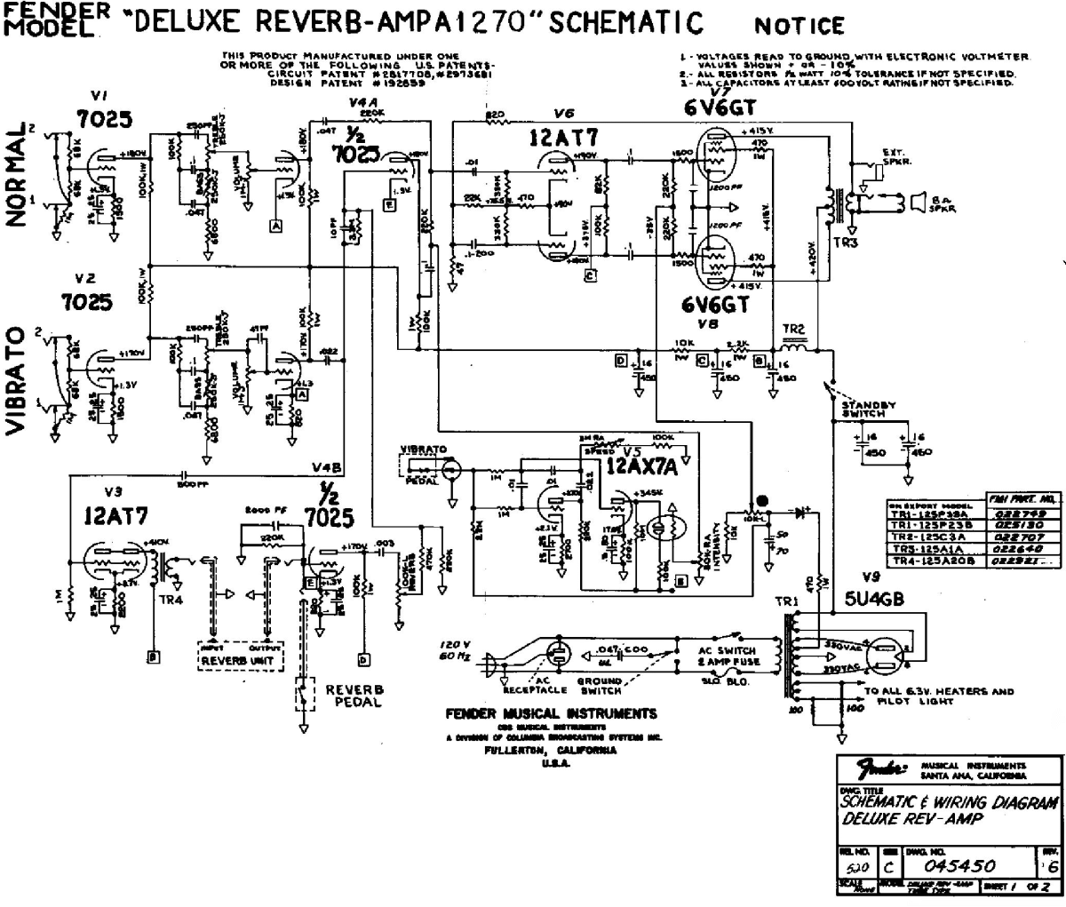
The "1270" in the model name comes from the circuit change date of 12-1970.
The first voltage dropping resistor was reduced from 10k to 2.2k for higher voltage for the phase inverter and preamp plates. This would add preamp and phase inverter gain which would drive the power tubes harder for more power tube distortion. First two filter caps moved back to the hot side of the standby switch which makes life easier on the rectifier tube by reducing standby switch induced filter capacitor inrush current. The reverb recovery driver's 220k grid leak is bypassed with a .002uF cap to remove reverb high frequency noise.
A1172 Silverface Deluxe Reverb 1967-77
Same as the AB868 above with minor tweaks.
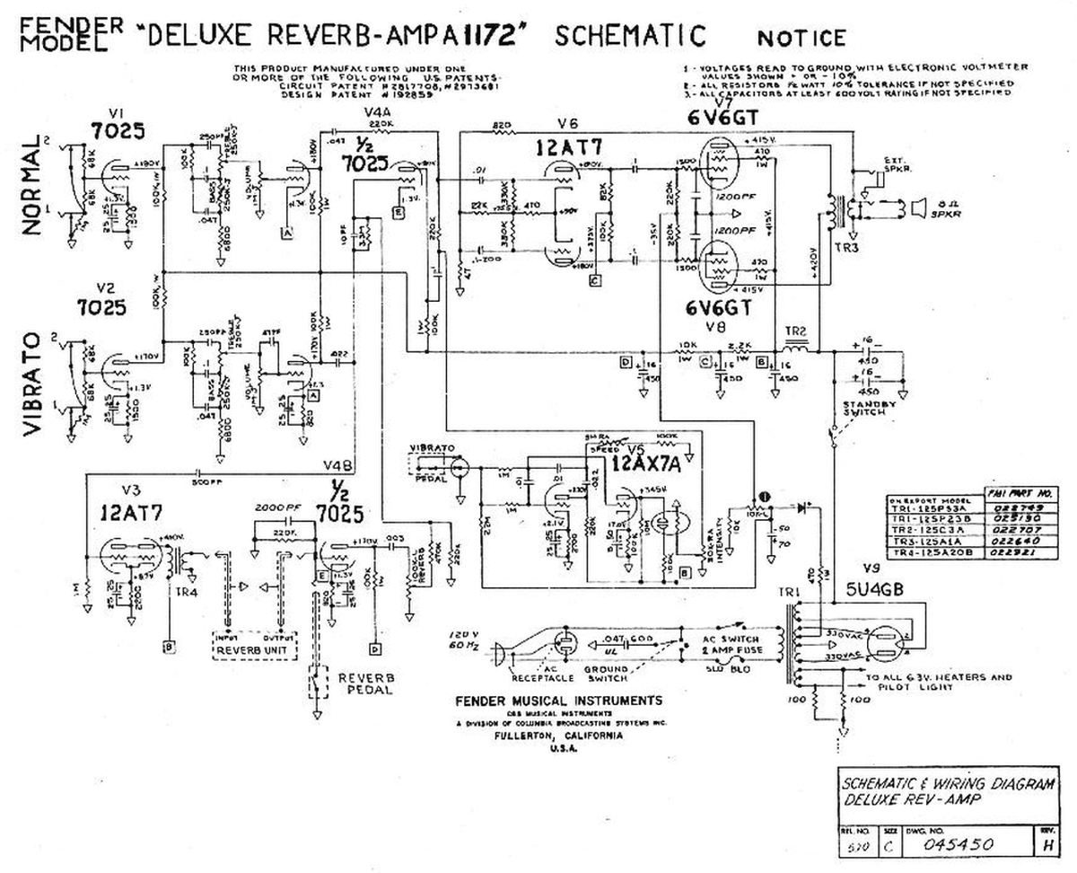
The "1172" in the model name comes from the circuit change date of Nov 1972.
Phase inverter input coupling cap increased from .001uF to .01uF to extend bass frequencies. Phase inverter grid leak resistors dropped from 1M to 330k to reduce preamp gain. First voltage dropping resistor reduced from 10k to 2.2k for higher phase inverter plate voltage ("C" or B+3 node) to increase phase inverter gain. These last two changes reduce phase inverter distortion and increase power tube distortion which usually sweetens an amp's overdrive tone. 1200pF stability capacitors added to the power tube grids to control oscillation caused by less than stellar lead dress. First two filter caps moved to the cold side of the standby switch (not a good move in my opinion because standby switch inrush current is increased).
Silverface "Push/Pull Volume Boost" Deluxe Reverb 1977-82
This Deluxe Reverb gets a bad rap but leave the Volume Boost switch alone and you end up with just minor tweaks from the A1270 above.
Note the "Push/Pull" switch just to the right of the 12AT7 reverb driver tube. When pulled the reverb driver output (dry signal) is used as an additional gain stage and the reverb transformer's output is sent around the reverb circuit and injected into the reverb out wire resulting in a dry signal gain boost. Three position ground switch. Reverb driver goes from 2.2k fully bypassed cathode resistor to unbypassed 580 ohm. Removing the bypass cap would lower gain but reducing the size of the cathode resistor would increase gain. The changes were made because the reverb driver pulls double duty as a gain stage with the Push/Pull switch engaged. First two filter caps moved back to the cold side of the standby switch. Bias filter cap increased from 50uF 70v to 80uF 75v to decrease hum.
Rivera Deluxe Reverb II 1982-86
The Deluxe Reverb II is very different than all the other Deluxe Reverbs. Tremolo was removed but gain, master volume and presence controls were added. Pedal controlled channel switching was added and a solid state rectifier replaced the rectifier tube (boo). Output dropped slightly to around 20 watts.
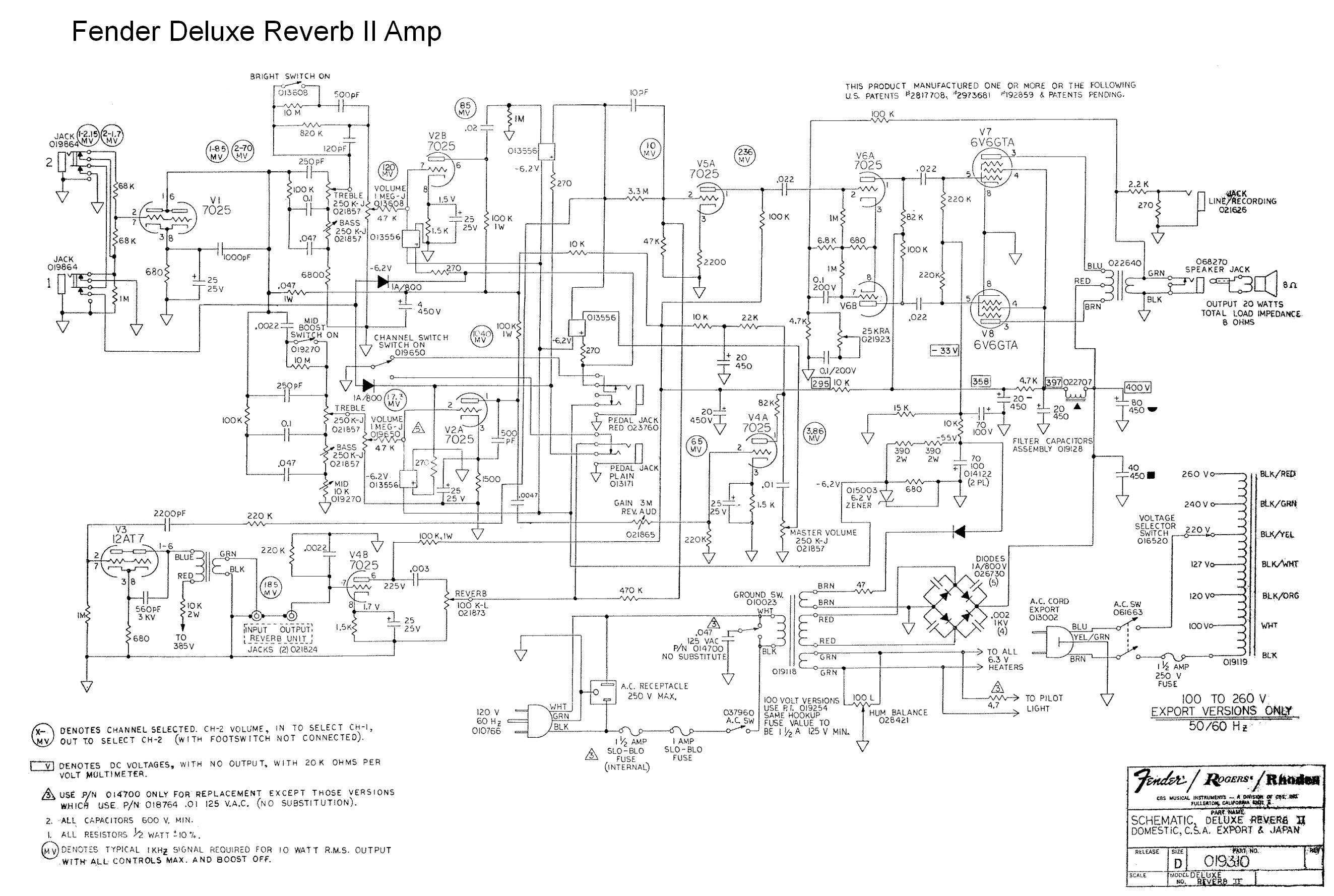
Click image for full size schematic.
It's a complicated, modern amp that gets mixed reviews. It looks like an abomination to me ;)
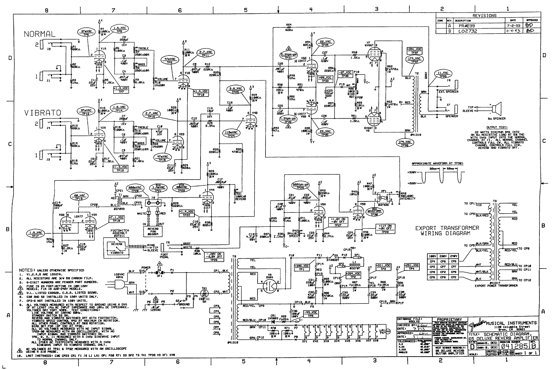
65 Deluxe Reverb Reissue 1993-Present
The AB763 circuit on a PCB instead of an eyelet based circuit board. Amp repairs and modifications with a PCB can be more difficult. Download the Reissue '65 Deluxe Reverb Service Manual. See the 65 DRRI modifications at the AB763 Modifications page. It's pretty easy to convert a 65 DRRI into a 68 CDR.
'65 Deluxe Reverb Reissue Signal Path
Click image for full size clean schematic.
65 Deluxe Reverb Reissue PCB Layout
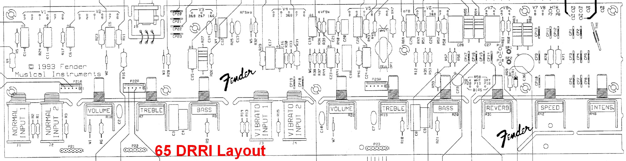
Click the image for the full size layout.
Comparison to AB763 Deluxe Reverb: Convenient combined reverb & tremolo footswitch using three conductor TRS cable. Schematic calls for 5AR4 which is a GZ34 equivalent. A power transformer with lower voltage output is used giving 24v lower "A" or B+1 voltage. This was probably done to compensate for higher modern wall voltages. The slightly lower voltage would "soften" the amp and decrease output power slightly. The lower voltage is also easier on all the tubes. The "A" or B+1 filter caps of 220uF 100v and 47uF 500v are in series which roughly equals a 39uF 600v cap which is slightly more than the AB763's 32uF. The bias filter cap increased from 25uF 50v to 100uF 100v to reduce hum. A modern three prong power cord is used.
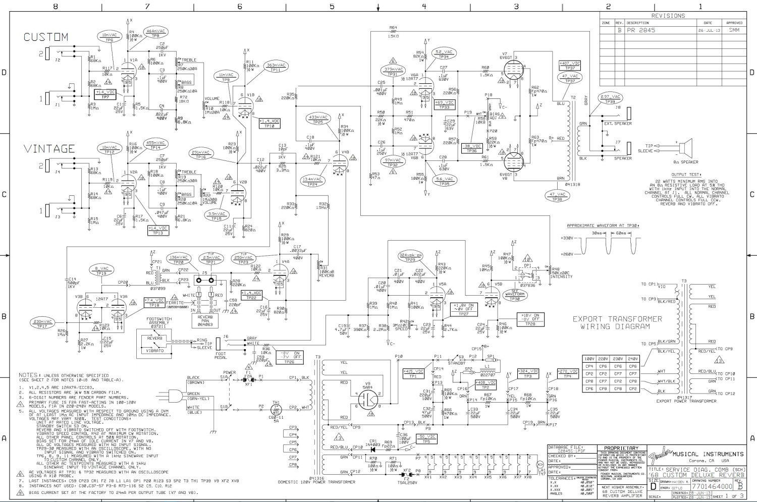
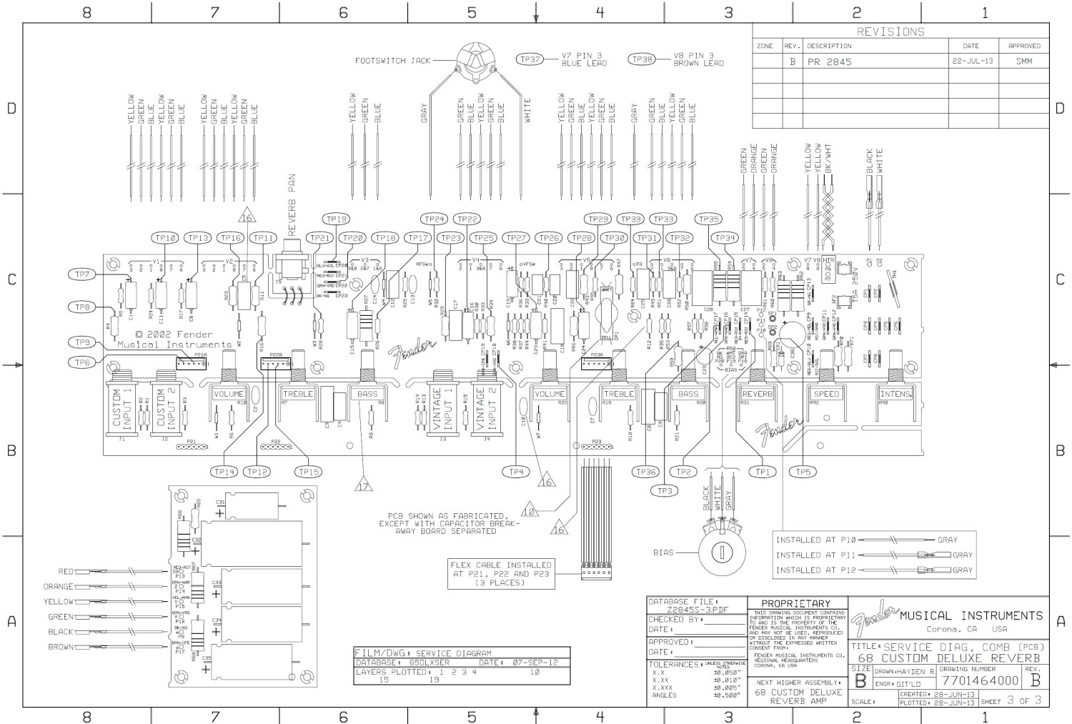
68 Custom Deluxe Reverb (68 CDR Reissue) 2013-Present
Differences from 65 Deluxe Reverb Reissue: Reverb and tremolo are available on both Vintage & Custom channels and both channels go through the third preamp gain stage V4B so both channels are now in phase so you can jumper channels for a thicker tone. Negative feedback is cut in half. Vibrato channel bright cap removed. Fender describes the Custom channel as having a "modified" Bassman tone stack. 10k grid stopper resistors are added to the 2nd and 3rd preamp stages to help control overdrive behavior. British voiced speaker. The 68 CDR's PCB circuit board is very similar to the 65 DRRI's layout above in the previous section. 68 CDR mods are here.
68 CDR Schematic
Click the image for the full size schematic.
68 CDR Layout
Click the image for the full size layout.
Tone Stack Comparison
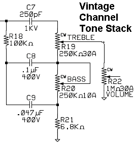
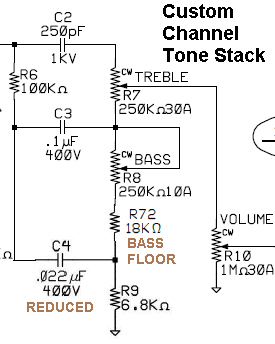
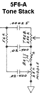
68 CDR Vintage channel on left, Custom channel in center, 5F6-A Bassman on right. The center Custom channel tone stack is supposed to be a modified version of a Bassman tone stack but I don't see much similarity with THE Bassman stack. The Bass cap is five times larger, the slope resistor is 80% larger, the Bass pot is 75% smaller, two Mid resistors replace the 25k Mid pot to simulate a 25k pot set to 6.8k. The added 18k resistor also acts as a "bass floor" to limit how low you can set the bass. The treble control is a high-pass filter and the bass and mid controls are band-pass filters with the 100k slope resistor setting the upper frequency limit and the bass pot and 6.8k mid resistor setting the lower.
Tone Stack Mid Cap Change
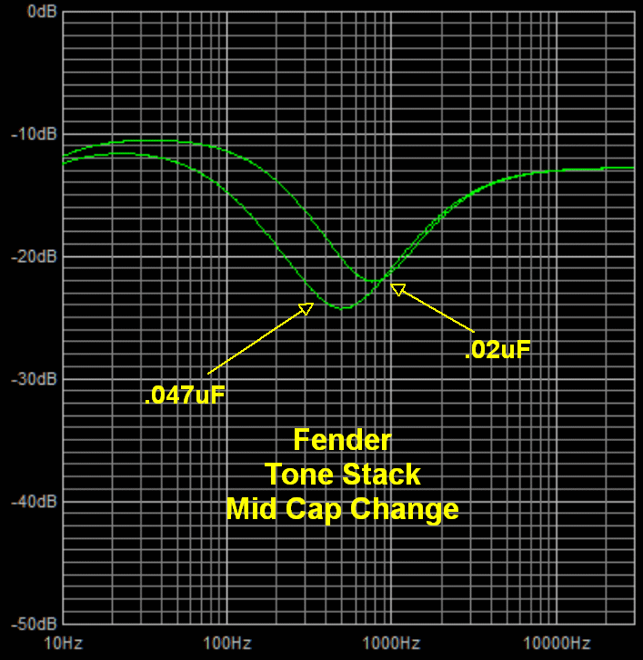
The only difference between the two 68 CDR tone stacks is the 18k resistor and the middle tone cap. The Custom channel's reduced .02uF middle cap shifts the mid tone control frequency band higher and reduces the mid scoop. Chart is from the Duncan Tone Stack Calculator. Download the 68 CDR Vintage channel, 68CDR Custom channel and 5F6-A Bassman Duncan Tone Stack Calculator files.
Customizing and adding the effects to the old "Normal" channel makes the 68 CDR more versatile because many Deluxe Reverb players never used the Normal channel. The 68 CDR's Vintage channel is the old "Vibrato" channel. The bright cap on the Vibrato volume pot has been removed to reduce ice pick highs. The added tone stack 18k resistor acts as a "bass floor" and sets the minimum bass. Some 68 CDR owners have jumpered around this resistor to allow them to set a lower bass level. The negative feedback resistor is increased from 820 ohms to 1.5k to cut feedback in half, thicken the clean tone and bring on earlier distortion (reduce headroom). British voiced 12” Celestion G12V-70 speaker. Blue jewel light (sweet!). Reviews are very favorable.
It's pretty easy to convert a 65 DRRI into a 68 CDR.
Edge Deluxe Reissue
The new reissue Edge Deluxe has a hand wired eyelet board similar to the original 5E3.
It comes with a $270, 12-inch, 15 watt Celestion Blue G12 Alnico speaker with 100dB sensitivity so it's louder than 5E3 vintage speakers with their typical sensitivity of around 95dB. The Celestion Blue came in the original Vox AC30 so it sports a classic British voice.
Its volume pots' taper has been made more logarithmic (less linear) to slow the action of the knob and make the volume control more usable. I believe this is a minor tweak and not worth the effort to swap out the volume pots even if you could source the correct taper pots.
The Edge Deluxe Chassis
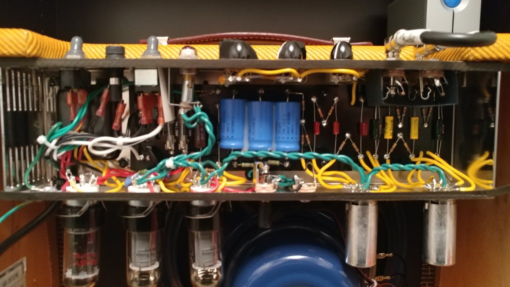
Photo by Skip.
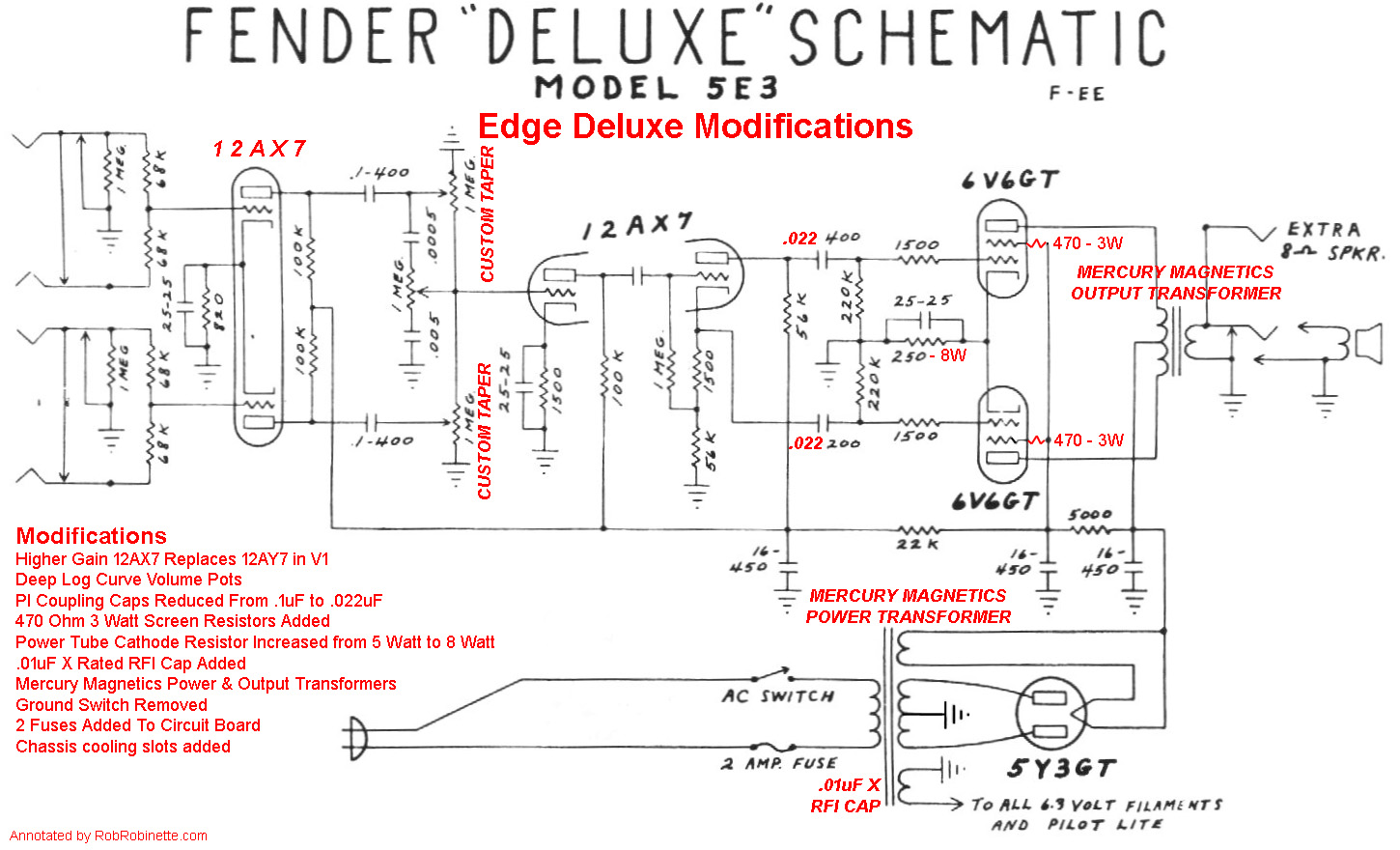
Both volume pots, both phase inverter caps and the V1 preamp are different from a standard 5E3 Deluxe. Both transformers are from Mercury Magnetics. Screen resistors have been added to the power tube sockets.
The normally .1uF phase inverter coupling caps are reduced to .022uF to tighten the bass response. The smaller cap filters out unneeded very low guitar frequencies.
A higher gain 12AX7 is used in V1 instead of the original's 12AY7 (even though the Edge's tube sheet says 12AY7). This limits playing clean to very low volume knob settings. If you have an Edge Deluxe I recommend you try an Electro Harmonix 12AY7 in V1.
The Edge Deluxe also has added 470 ohm screen resistors to the power tube sockets. These resistors help protect the power tubes from excessive screen current during extended overdrive sessions and also slightly alter the overdrive tone, typically for the better. For more info on how screen resistors affect overdrive tone see this.
All the amp's transistors are modern carbon film resistors instead of the noisier, period correct carbon composition found in the original 5E3. Carbon film resistors generate less hiss than carbon comp resistors.
The power tube cathode resistor is a Brown Devil 250 ohm 8 watt where the original used a 250 ohm 5 watt resistor.
The Edge also comes with very nice Mercury Magnetics Output and Power Transformers. The output transformer is labeled 0073302000. The power transformer is not labeled.
Fender added two additional fuses to the circuit board for power transformer protection.
A .01uF Class X rated cap has also been added most likely to help reduce power line noise.
"Flying" tube heater wires are run above the tube sockets instead of down against the chassis like in vintage 5E3 amps.
Cooling slots have been cut into the rectifier end of the chassis.
Protective rubber switch dust covers and the Edge’s hand-designed grille logo badge were added.
The cab's tweed fabric is lacquered.
Other than that it's a standard tweed Deluxe.
By Rob Robinette
Want to learn more about how tube guitar amps work? See my How Tube Amps Work webpage.
References
RCA Corporation, RCA Receiving Tube Manual, RC30.
Merlin Blencowe, Designing Tube Preamps for Guitar and Bass, 2nd Edition. This is my personal favorite tube amp book.
Merlin Blencowe, Designing High-Fidelity Tube Preamps
Morgan Jones, Valve Amplifiers, 4th Edition.
Richard Kuehnel, Circuit Analysis of a Legendary Tube Amplifier: The Fender Bassman 5F6-A, 3rd Edition.
Richard Kuehnel, Vacuum Tube Circuit Design: Guitar Amplifier Preamps, 2nd Edition.
Richard Kuehnel, Vacuum Tube Circuit Design: Guitar Amplifier Power Amps
Robert C. Megantz, Design and Construction of Tube Guitar Amplifiers
Neumann & Irving, Guitar Amplifier Overdrive, A Visual Tour It's fairly technical but it's the only book written specifically about guitar amplifier overdrive. It includes many graphs to help make the material easier to understand.
T.E. Rutt, Vacuum Tube Triode Nonlinearity as Part of The Electric Guitar Sound
[ How Amps Work ] [ Overdrive ] [ 5E3 Mods ] [ 5F6A Mods ] [ AB763 Mods ] [ DRRI & 68 CDR Mods ] [ How the 5E3 Deluxe Works ] [ How the AB763 Works ] [ AB763 Models ] [ Tube Bias Calculator ] [ Amp Troubleshooting ] [ Deluxe Models ] [ Deluxe Micro Amp ] [ Bassman Micro Amp ] [ Champ Micro Amp ] [ My 5E3 Build ] [ Reverb & Tremolo ] [ SixShooter ] [ Spice Analysis ] [ VHT Special 6 Ultra Mods ] [ Telecaster Mods ] [ Android Tube Bias Calculator App ] [ The Trainwreck Pages ] [ Fender Input Jacks ] [ B9A Prototype Board ]