Tube Guitar Amp Overdrive
By Rob Robinette
While distortion is to be avoided at all costs in audio amplifiers, it is the most important aspect of guitar amplifier design. The primary reason tube guitar amplifiers are favored over solid state amps is their overdrive tone. Very few people can tell the difference between a high quality tube and solid state guitar amp in a blind test when playing clean. But push the amp into overdrive distortion and the difference can be stark. Tube overdrive tends to exhibit softer, asymmetric clipping, even order harmonic distortion with time-variance and nonlinear distortion that is almost impossible to mimic using solid state devices. Electrical engineers will tell you that solid state amplifiers can faithfully mimic tube clean and overdrive tone but I say why bother with something that is trying to mimic the real thing. So I admit up front I have a tube guitar amplifier bias.
NOTE: On this page I do not use "conventional current flow." Conventional flow assumes current flows from positive to negative because Benjamin Franklin guessed wrong on the direction of electron flow. On this page I describe the actual flow of electrons from negative to positive and from cathode to plate because with tubes I believe it's important to understand the actual movement of electrons through the circuit.
Table of Contents
What is Distortion and Overdrive
Grid Current, Bias Excursion, Grid Clipping and Blocking Distortion
Time-Variance Linear Distortion
Output Transformer and Voice Coil Flyback Voltage Spikes
A Brief History of High Gain Amps
Quick Review of How Tube Amplifiers Work
 This
short review may help you understand the following discussion on tube overdrive.
This
short review may help you understand the following discussion on tube overdrive.
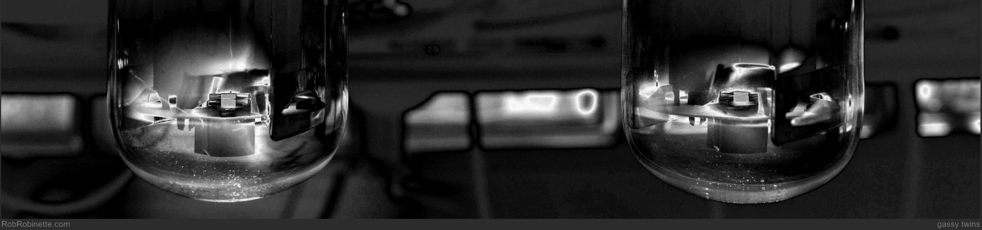
In a vacuum tube negatively charged "space charge" electrons are knocked off the hot cathode by heat related kinetic energy. Once free they flow through the control grid to the positive charged plate. It's the high voltage DC on the plate that pulls space charge electrons coming off the cathode through the control grid and onto the plate. The guitar AC (alternating current) signal voltage charges the tube's control grid which acts as the control valve of the tube. During non-overdrive conditions the control grid always stays at a negative voltage compared to the cathode.
The no signal voltage difference between the grid and cathode is the bias voltage. The bias voltage sets the tube's operating point. You must understand this concept to understand tube amplifier overdrive. Anything other than the guitar signal that changes the voltage difference between the grid and cathode shifts the bias voltage and operating point.
Like electrical charges repel one another so when the control grid has a strong negative signal voltage (negative voltage = excess electrons) the electrons on the grid are packed together tightly and repel the space charge electrons in the tube and slow their flow through the grid to the plate. Negatively charged electrons don't like to flow through a negatively charged grid. Opposite electrical charges attract one another so the positive plate pulls the negative charged space charge electrons to it.
When the grid has a positive signal voltage (positive voltage = scarcity of electrons) it has fewer electrons on it so its blocking power is reduced and space charge electrons flow through the grid to the plate at a higher rate.
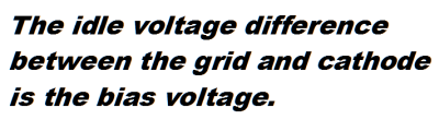
Standard Vacuum Tube Preamp Circuit
Guitar signal voltage enters the tube on the left at "AC Signal In" and exits on the right at "AC Signal Out". The signal flows through the Grid Stopper Resistor onto the tube's Grid which controls the electron flow from the Cathode to Plate. The signal exits the circuit through the Coupling Cap and flows to the next circuit which can be another gain stage, tone stack, etc. This tube is a 'triode' which means it has three electrodes, the cathode, grid and plate. Space charge electrons flow from the cathode through the grid to the plate.
A positive voltage on the tube's control grid pulls electrons off the grid and spreads them out. A negative voltage on the grid pushes electrons onto the grid and packs them tighter together.
The signal voltage on the grid is amplified because a small voltage change on the grid creates a large electron flow change through the grid which leads to a large voltage change on the plate. The voltage changes on the plate are the amplified guitar signal. See How Tubes Work for more information.
What is Distortion and Overdrive
An audio signal is distorted when there is a change in signal wave shape from input to output. Since tube amps' transfer curves are nonlinear they will always cause some distortion even when played "clean." But this low level distortion adds texture and warmth and fattens up the tone. Perfectly amplified electric guitar with no distortion can sound cold and sterile. That's why solid state audio amps make electric guitar sound so bad.
Guitar AC Signal Voltage
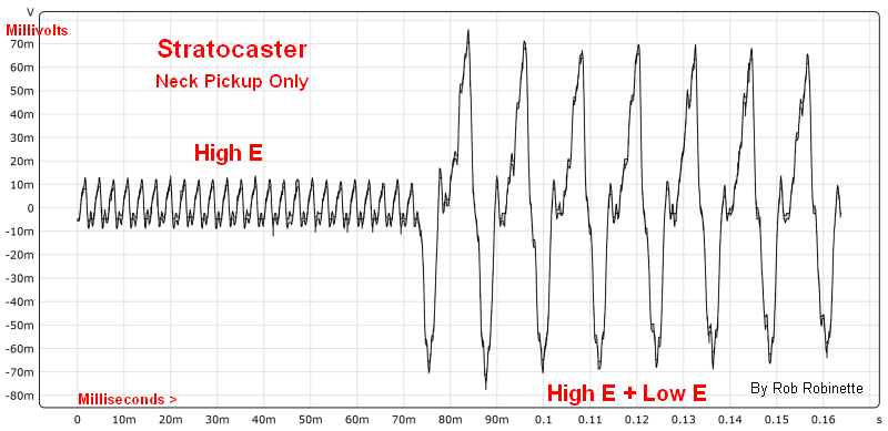
Fender Stratocaster connected directly to an oscilloscope. Each 'wave' on the oscilloscope is caused by one string vibration. The left side of the graph shows a high open E string pluck followed by a pluck of the low open E. Voltage is on the left scale and time runs along the bottom. The top half of the signal is positive voltage (positive signal lobe) and the bottom half is negative (negative signal lobe). The guitar's signal voltage and current alternate between positive and negative.
If an amplifier's transfer curve is a straight line (linear) you will have no distortion. The output signal will be an exact, but larger version of the input. Tube amplifiers' transfer curves are not straight lines, they are non-linear so tube amps always generate nonlinear distortion, even when played "clean". Nonlinear distortion always creates harmonic and intermodulation distortion too.
6V6 Transfer Curve
![]()
A tube transfer curve is a plot of control grid voltage vs. plate current. Since the transfer curves are not straight lines or linear, nonlinear distortion will be created during amplification even at low volume.
When a tube amp is pushed into overdrive it moves to the less linear (more curvy) part of the transfer curve and creates more nonlinear distortion along with harmonic and intermodulation distortion.
Harmonic distortion is created when nonlinear distortion is present. It consists of overtones or "higher frequency echoes" of the original sound. Harmonic distortion is always higher in frequency than the original tone (no subharmonics are created). Harmonic distortion's overtones are whole number multiples of the original tone. A guitar low E string vibrates at 82.4 Hz (Hertz or vibrations per second) but harmonic distortion will add overtones of 164.8, 247.2, 329.6 and so on. The original 82.4Hz guitar string tone is considered the "1st harmonic". 164.8 is the 2nd harmonic and 329.6 is the 4th. Both are even order harmonics. 247.2 is the 3rd, odd harmonic. Even order harmonics (2nd, 4th, 6th. . .) tend to sound more pleasing to our ear compared to odd order harmonics. Too much harmonic distortion can add too much high frequency for "ice pick" highs.
Intermodulation distortion (IMD) is created when nonlinear distortion + two or more tones are present. The multiple signals generated by harmonic distortion create intermodulation distortion so a pure sine wave passed through a tube amp will always have nonlinear, harmonic and intermodulation distortion. Intermodulation distortion not only has higher frequency overtones but also has lower frequency subtones which can fill in the low end of a guitar signal during overdrive.
Why do most amplifier high gain channels sound thin and anemic when played clean? Because to get the best overdrive tone you have to filter the guitar signal and remove a lot of the bass to prevent a muddy, boomy overdrive tone and prevent blocking distortion. But drive the high gain channel into overdrive and harmonic and intermodulation distortion fill in both the bottom and top end for a nice fat overdrive tone. A high gain guitar amplifier must be voiced to handle the additional signal components generated by nonlinear, harmonic and intermodulation distortion during overdrive. Keep this in mind next time you evaluate an amp with a high gain channel.
Overdrive distortion is a type of distortion that occurs when the AC guitar signal voltage swing is too large and the output signal is clipped causing the generation of harmonic and intermodulation distortion. Vacuum tube clipping can occur due to cutoff and/or grid clipping. When an AC signal's lower, negative lobe is too large it is clipped or flattened by cutoff. Cutoff occurs when the input signal's negative lobe on the grid goes so negative that all electron flow through the tube is shut off. Even if the signal on the grid goes more negative the output signal cannot respond because electron flow is already shut off so the output signal is capped and flattened. This change in wave shape from input to output is overdrive distortion.
Tube amplifiers don't actually clip due to true saturation (unrestricted electron flow from cathode to plate) because as the control grid approaches a positive voltage the signal on the grid is clipped well before the point of true saturation. For tube amps the term "saturation" really means the onset of grid clipping.
Grid Current, Bias Excursion, Grid Clipping and Blocking Distortion
Understanding grid current is important to understanding tube overdrive distortion. Electrons flowing from the control grid upstream can cause bias voltage excursion, cutoff clipping, grid clipping and blocking distortion, typically in that order.
During normal operation a tube flows negatively charged electrons from its cathode, through the control grid, to the positively charged plate. Since opposite electrical charges attract, the negative charged space charge electrons are attracted to the positive plate. The tube's bias voltage places the control grid at a negative voltage compared to the cathode voltage. Since like electrical charges repel one another a negatively charged grid has excess electrons which repel the negatively charged space charge electrons in the tube. The more negative electrons on the grid the more blocking power the grid exerts on the space charge electron flow.
When a large input signal voltage hits the control grid the positive lobe of the signal brings the grid toward a positive voltage. As the grid becomes more positively charged the more negative charged space charge electrons will be attracted to it in the same way space charge electrons are attracted to the positive plate. Remember, a positive voltage is a scarcity of electrons so a positive guitar signal on the grid pulls electrons off the grid. If the pull is too hard it will actually start pulling space charge electrons in the tube onto the grid and into the input circuit. This is an important concept to understand so I'll say it again:
When a guitar audio signal is too large for a tube circuit the excess positive voltage on the grid will pull space charge electrons in the tube onto the control grid. This is how grid current begins to flow.
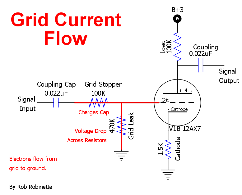
As space charge electrons are captured by the grid, electrons will begin to flow upstream toward the grid leak resistor and coupling cap. This is known as grid conduction or grid current. Grid current is direct current (DC) and will charge an upstream coupling cap with negative voltage and cause a voltage drop across a grid stopper and grid leak resistor.
Grid current electrons want to flow to ground but the grid leak resistor restricts their flow so they build up on the grid and inside the coupling capacitor. This "build up" of electrons is a negative voltage bias excursion.
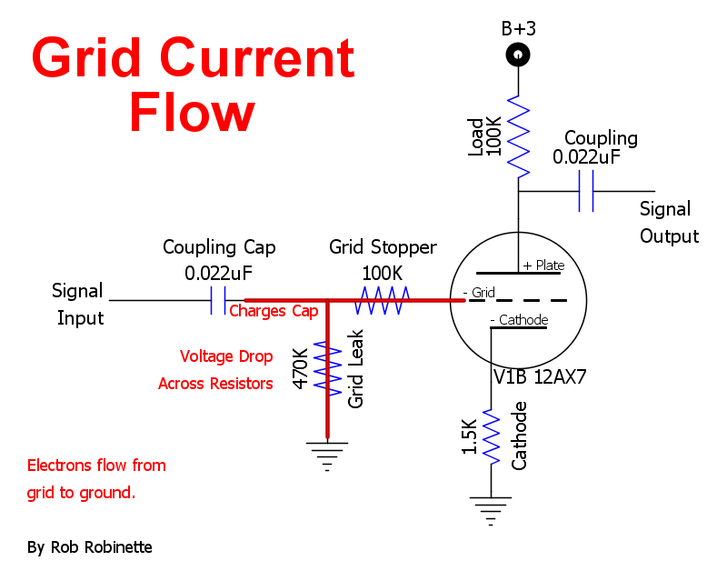
Typical second preamp gain stage. During overdrive electrons are captured by the tube's grid and flow through the 100K grid stopper resistor to charge the coupling cap and through the grid leak resistor to ground. The grid stopper and grid leak resistance restrict the flow of electrons causing a buildup of electrons on the grid. This buildup of electrons on the grid repel the space charge electrons that are trying to flow from the cathode to plate. This build up of negative electrons is a negative voltage bias excursion.
Bias Excursion
Grid current will push the grid more negative which shifts the grid's bias voltage toward cutoff. In other words as the electrons flow from the grid, through the grid stopper resistor to the coupling cap and through the grid leak resistor a voltage drop forms across the resistors which shifts the grid bias voltage negative toward cutoff. As the bias voltage changes, the tube's operating point changes. This dynamic grid voltage bias excursion is very nonlinear so it generates nonlinear distortion along with harmonic and intermodulation distortion.
As grid current shifts the bias voltage towards cutoff it makes it more likely that there will be more negative lobe cutoff clipping than positive lobe clipping.
Asymmetric Soft Clipping
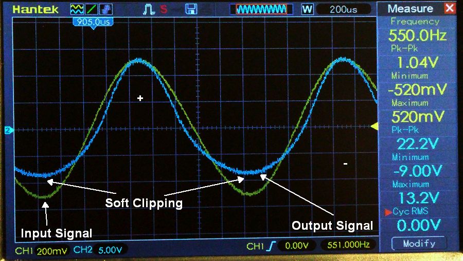
The sine wave input signal is shown in green and the clipped output signal is shown in blue. The bottom, negative lobe of the output signal has been rounded off and flattened due to cutoff clipping. Since the lower lobe has been distorted and the upper lobe has not this is an example of asymmetric clipping. The rounded shape of the lower lobe clipping makes it soft clipping. Soft asymmetric clipping generates pleasant sounding even order harmonic distortion. Soft asymmetric clipping is the most common form of tube overdrive distortion and is what separates it from solid state transistor distortion. Photo by Boris Dugonich.
To summarize, an overdriven input signal's positive charge on the control grid will lead to it being attractive to the space charge electrons flowing through the tube. As the space charge electrons accumulate on the grid and begin to flow, the grid voltage shifts negative toward cutoff--this is a grid bias voltage excursion. This voltage shift makes it more likely that the negative signal lobe will get clipped at cutoff. When one signal lobe is clipped more than the other the clipping is asymmetric.
Grid Clipping
Grid clipping occurs when grid current flows into the input circuit and loads down the positive lobe of the input signal. Grid clipping distorts the input signal. When grid current begins to flow the grid current caps the grid's maximum positive voltage which clips the positive lobe of the input signal on the grid. A larger positive signal voltage simply causes more grid current to flow and does not add to the flow of electrons to the tube's plate so the output positive lobe is clipped.
The tube will then faithfully amplify the clipped input signal and send it out the plate. In other words when grid current begins to flow it greatly reduces the tube's input impedance and the positive half of the input signal is loaded down to the point of clipping.
A tube amp circuit with global negative feedback will typically grid clip harder, with sharper waveform corners, than the same amp without feedback. The transition from clean to distorted also tightens up with negative feedback. The Marshall JTM45 is an almost exact copy of the Fender 5F6-A Bassman but the Marshall uses almost three times more global negative feedback. This is the main reason the overdrive tone of the JTM45 seems more "aggressive" than the 5F6-A.
If grid current flows long enough it will charge an input coupling capacitor. The coupling cap acts as a reservoir to store the electrons flowing from the grid. This reservoir of electrons will slow the voltage change back to normal bias (bias recovery). A certain amount of bias excursion can lead to a pleasing overdrive dynamic but too much bias excursion can be a problem.
Here's an online Power Tube Grid Bias Excursion Calculator.
Blocking Distortion
Excessive grid current can cause a sufficiently negative bias voltage excursion to cause blocking distortion. Blocking distortion can cause a complete dropout of the output signal voltage when the positive signal lobe is grid clipped while simultaneously the negative signal lobe is clipped at cutoff caused by bias excursion (see Randall Aiken's explanation of blocking distortion for more info). Unlike most other forms of overdrive distortion, blocking distortion always sounds bad. "Farting out" is a popular term used to describe severe blocking distortion.
Because grid current causes a change in the bias voltage, grid current alters the flow of electrons from the cathode which can charge or discharge a cathode bypass capacitor so a bypass cap can affect bias excursion depth and recovery time. The larger the bypass cap value, the longer the cap can support a bias excursion. Using a very small or no bypass cap will shorten bias excursion recovery time. This is another reason modern high gain preamps use no or very small cathode bypass caps such as the .68uF found in the Marshall JCM800 preamp shown below. This effect is also why high gain amplifiers rarely use cathode biased power amps.
Controlling Grid Current and its Effects
Attenuating Voltage Divider
Heavy grid current and the blocking distortion it causes can be controlled by limiting a gain stage's input signal with an attenuator. The Marshall JCM800 amplifier uses a 470k/470k voltage divider in front of its V2A preamp gain stage to cut the input signal in half (6dB of attenuation) to keep from over overdriving the stage.
JCM800 Attenuating Voltage Divider
Red arrows point to the two 470k resistors that form the voltage divider. The guitar signal is cut in half by the two resistors. The upper 470k resistor also functions as a grid stopper to slow the .022uF coupling cap's charge time. A 470pF bright cap is in parallel with the upper resistor to allow high frequencies to bypass the resistor to keep the tone bright. The lower 470k resistor is also V2A's grid leak resistor. At 470k it is smaller than usual 1M which bleeds more grid current to ground and quickens the coupling cap's discharge time which helps prevent blocking distortion.
Grid Stopper Resistor
Adding a grid stopper resistor will slow the flow of grid current by slowing the movement of captured electrons off the grid. But slowing the flow off the grid causes the electrons to build up on the grid and cause a bias excursion toward cutoff. So a grid stopper resistor reduces grid current and grid clipping but increases bias excursion. Adding a grid stopper resistor or increasing its resistance will shift the overdrive distortion from grid clipping toward bias excursion and cutoff clipping. A smaller value grid stopper will allow more grid current and grid clipping but reduce bias excursion. You can alter the value of the grid stopper to control the balance between grid clipping and cutoff clipping to tune the overdrive tone.
Effect of Grid Stopper Position
When the grid stopper resistor is placed before the grid leak resistor as shown above it forms a voltage divider for the incoming AC guitar signal and can be used to attenuate the signal to control gain. When the grid stopper is placed after the grid leak as shown below it no longer forms a voltage divider for the guitar signal but it does form a voltage divider for grid current which can be used to prevent blocking distortion.
Dual Grid Stoppers
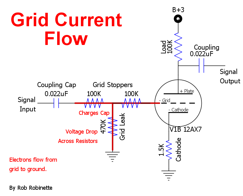
We can use a grid stopper resistor before and after the grid leak to attenuate the guitar signal with the first grid stopper and control grid current with the second.
Coupling Cap Value
Another way to control grid current's effect is increasing the coupling cap charge time or decreasing the cap's discharge time. The cap's charge time can be slowed by placing a grid stopper resistor between the grid and coupling cap. In the JCM800 schematic above the upper 470k "Attenuator" resistor also functions as a grid stopper resistor to increase the charge time of the .022uF coupling cap.
The coupling cap's discharge time can be quickened by reducing the value of the grid leak resistor but this also attenuates the input signal. In the JCM800 above V1A uses a 470k grid leak (normal is a 1M) to quicken the cap's discharge time. Power tube grid leak resistors are usually a much smaller resistance value than preamp grid leak resistors (100k or 220k vs. 1M) because of the greater amount of grid current they must sink.
Since low frequencies carry more energy they will charge a coupling cap more efficiently. Reducing the size of the coupling cap will reduce the bass content of the signal and slow the cap's charge time. When the input signal hits a small coupling cap bass frequencies are reduced downstream so the tube grid gets a filtered signal with less bass frequencies. When grid current begins to flow upstream to charge the cap it has less bass frequency energy to charge the cap which slows its charge time. This is one reason why high gain amps often use very small .0022uF coupling caps. The other reason small coupling caps are used is to reduce bias excursion recovery time which also helps prevent blocking distortion. As stated earlier using small cathode bypass caps can also reduce bias excursion recovery time.
The Fender 5E3 tweed Deluxe uses huge .1uF coupling caps, no preamp grid stoppers, large 1M grid leaks and large 25uF cathode bypass caps which allow grid current to run wild for a perfect storm for "farting out" with extreme blocking distortion. Compare that with the Marshall JCM800 above with its .022uF coupling caps, 470k grid stopper, 470k grid leak and tiny V1B .68uF cathode bypass cap (and no bypass cap on V1A & V2A) and you'll see why the Marshall sounds so sweet during high gain overdrive.
Time-Variance Nonlinear Distortion
The interaction of grid current and coupling capacitor charging is a form of time-variance nonlinear distortion, meaning the distortion varies over time as the coupling cap charges and discharges. This time-variance can be controlled by altering the value of the coupling cap, grid stopper and grid leak resistors. A little grid current and the resulting drop in bias voltage toward cutoff is a dynamic source of sweet sounding asymmetric soft cutoff clipping. The dynamic bias excursion caused by grid current and coupling cap interaction at the right level can be magical and is the hallmark of guitar tube amplification and its sweet overdrive tone.
Asymmetric Clipping, Duty Cycle Modulation and Even Harmonics
If a tube is biased perfectly between grid clipping and cutoff it is possible to get equal (symmetric) clipping where both the positive and negative lobe of the guitar signal are equally cut off and flattened. But even when biased perfectly bias excursion will cause asymmetric clipping so asymmetric clipping is much more common in tube amplifiers than symmetric clipping. Asymmetric clipping generates ear pleasing even order harmonics and minimizes nasty sounding odd harmonics. When a guitarist pushes a tube amp hard enough to get symmetric clipping, using volume control or pick intensity, odd order harmonics greatly increase making the overdrive tone sound more "angry".
From Radiotron Designer's Handbook 4th Edition:
The distortion and power output of type 6L6 beam power valve are plotted against load resistance in Fig. 13.30 (below). The second harmonic is 9.6% at the rated load resistance, the third harmonic only 2.4% and all higher harmonics negligible. At lower load resistances the second harmonic rises, although not seriously, the third harmonic decreases steadily, and all higher harmonics are negligible--the overall effect being quite satisfactory. At higher load resistances the performance is not good, and the overall effect is roughly the same as with a pentode.
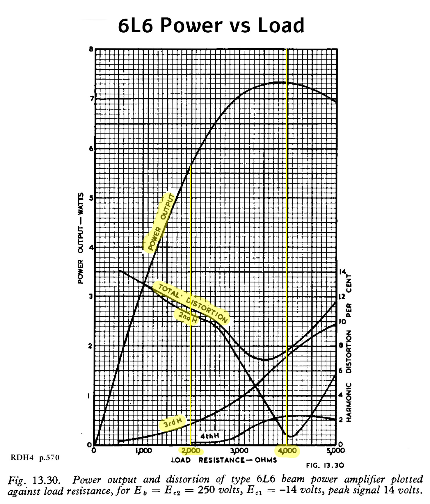
Note the relationship between even order harmonic distortion (2nd H and 4th H) versus odd order harmonic distortion (3rd H). As output power increases angry sounding 3rd order harmonics greatly increase. This chart is for a single-ended power amp so the equivalent push-pull load would be 8k plate-to-plate but typical 6L6 guitar amps use a 4k plate-to-plate output transformer which raises 2nd order harmonics and minimizes 3rd order.
Symmetric Soft and Hard Clipping
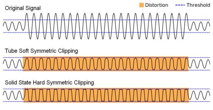
The top and bottom of the guitar signal is flattened by symmetric clipping. Since both the upper and lower signal lobes are clipped the same amount this is symmetric clipping. The tube's output signal upper, positive signal lobe has been clipped or flattened by grid clipping. The transistor's output signal upper, positive signal lobe has been clipped by saturation. The tube and transistor's lower, negative lobes have been clipped by cutoff. Note the sharp cutoff of hard clipping. Solid state amplifiers tend to clip harder than tube amplifiers which can sound more aggressive, raspy and less musical. (original image credit: Wikimedia Commons)
Marshall 1987 first preamp stages are biased warm and cool with 820 and 2.7K ohm cathode resistors. Marshall also employs a very large 320uF and very small .68uF cathode bypass caps, and .022uF and .0022uF coupling caps to differentiate the overdrive tones of the two channels. The Lead channel uses a very small .68uF cathode bypass cap and .0022uF coupling cap to reduce bias excursion recovery time and prevent blocking distortion.
With asymmetric clipping one signal lobe carries the undistorted musical content while the other lobe carries the distortion. Asymmetric distortion also adds sweet sounding even order harmonics while suppressing nasty sounding odd harmonics which makes the distortion sound more warm, musical and distinct from typical odd harmonic heavy solid state distortion. Asymmetric distortion is often described as sounding "creamier" with less fizz than symmetric distortion. "Fizz" is made up of high frequency odd order harmonic distortion accompanied by intermodulation distortion.
The Marshall 1987's normal channel biases the first gain stage off center to the warm side using a small 820 ohm cathode resistor. Biasing the two 1987 channels differently offers up different clean and overdrive tones on each channel.
It is common in tube guitar amplifiers that one gain stage will clip one signal lobe, then in a following gain stage the undistorted lobe will get clipped making the distortion more symmetric. It is common to use a warm biased gain stage after a cold clipper to preserve the undistorted signal lobe.
An AC guitar signal voltage causes electrons to alternate their direction through a circuit. During the positive half of the signal swing the electrons will move one direction and during the negative half they reverse course and move the other direction. With a symmetric AC signal the electrons will move the same distance back and forth through the circuit so there is no real movement of electrons on average, in other words there is no direct current (DC) component to the signal.
But an asymmetric AC signal voltage, where one lobe is larger than the other, will cause the movement of electrons more in one direction than the other which is a DC current. As an extreme example, if you completely clip off the positive lobe of an AC signal it becomes a pulsing DC signal--electrons move in a pulse in one direction. So asymmetric signal voltages have a DC component that will charge capacitors and cause voltage drops over resistors which can cause grid bias voltage excursion.
The term "duty cycle" can be used to describe asymmetric signal voltage. A symmetric signal has a balanced signal voltage of 50% positive and 50% negative so we say it has a 50% duty cycle. An asymmetric signal will have an imbalance of positive and negative signal voltage so its duty cycle has moved away from 50% so we can say the duty cycle has been "modulated." Solid state amplifier circuits usually maintain a 50% duty cycle during overdrive while tube circuits move away from a balanced 50% duty cycle which adds pleasant sounding even order harmonic distortion.
Cold Clipper Gain Stage
The cold clipper
gain stage is a very useful tool for voicing an amp's overdrive tone. It is used in many high gain tube amps to generate early and smooth sounding overdrive tone.For minimum distortion a tube should be biased halfway between cutoff (when all electron flow is stopped) and saturation (when electron flow is maxed out). A 1.5k cathode resistor for a typical tube amp 12AX7 triode gain stage is very close to center bias. A cold clipper's very large 10k to 39k cathode resistor sets a cold bias that leaves very little room on the cutoff side so the guitar signal can easily be clipped when the signal's negative lobe on the grid reduces electron flow through the tube and electron flow is shutdown completely. The cold clipper is designed to clip on the cold side of the operating point. This clipping is asymmetric because there's plenty of room on the saturation side of the bias point so the guitar signal's negative lobe is clipped while the positive lobe passes unmolested and carries the original musical content. Asymmetric clipping generates ear pleasing even order harmonics and minimizes nasty sounding odd harmonics. When a guitarist pushes a tube amp hard enough to get symmetric clipping, using volume control or pick intensity, odd order harmonics greatly increase making the overdrive tone sound more "angry", giving fingertip control of the guitar's "mood".
The Marshall JMC800 uses a cold clipper stage with an unbypassed 10k cathode resistor. Soldano likes to use a 39k cathode resistor for his cold clipper.
The cold clipper generates early, relatively low volume, smooth, musical preamp distortion that can be controlled by a master volume for high gain tone at lower volume. A cold clipper stage is a great way to enhance an amp's overdrive tone but even when not overdriven the cold clipper will add nonlinear, harmonic and intermodulation distortion to the clean tone because the operating point is down low in the curvy part of the average plate characteristics graph. This added distortion fattens up the clean tone.
Marshall Cold Clipper Load Lines
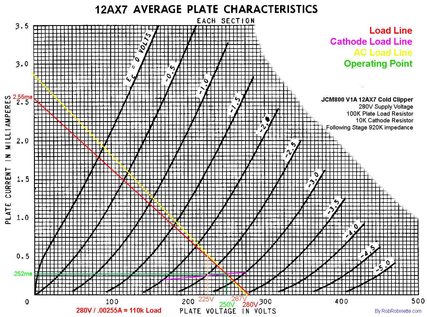
The operating point (intersection of green lines) is very low in the curvy end of the grid voltage lines so the negative half of the guitar audio signal is distorted even before clipping occurs. Signal clipping will occur with the negative lobe of the signal voltage much earlier than the positive lobe which will lead to early sweet sounding asymmetric cutoff clipping. For more info see How to Draw Tube Load Lines.
The cold clipper's asymmetric output signal can be clipped in later gain stages at high volume levels but note the gain stage following the Cold Clipper is biased warm with an 820 ohm cathode resistor (V2A). Because a guitar signal's phase is flipped after each gain stage, putting a warm biased stage after the Cold Clipper helps keep the distortion asymmetric by keeping the guitar signal's undistorted lobe clean. The warm bias leaves more room on the cutoff side to reduce clipping to the undistorted signal lobe.
You normally don't want to put a bypass cap on a cold clipper because the extra signal swing generated by the bypass cap will clip too early and too severely and sound "fizzy". The extra gain generated by the bypass cap can also cause early grid clipping in the following gain stage adding to the fizz fest.
The positioning of the cold clipper makes a big difference in when a preamp will begin clipping. With a fully bypassed cathode (25uF bypass cap) cold clipper as the first stage of a guitar amplifier we'll get much more gain compared to an unbypassed cold clipper. We'll have around 1.5v of swing to the cold side available so the signal straight from the guitar should not clip but the bypassed cold clipper will add harmonic and intermodulation distortion to thicken up the clean tone nicely.
The Marshall JCM800 with it's cold clipper in the second stage generates lots of preamp clipping which makes its pre-phase inverter master volume more functional. The master volume reduces the signal into the phase inverter and power tubes reducing their overdrive distortion but since the preamp is clipping we can get low master volume overdrive tone.
Placing the cold clipper in the third stage like in the Trainwreck Express allows the hotter signal from the second stage to generate even earlier and more gnarly clipping in the cold clipper. We end up with a much more aggressive preamp with a lot less headroom.
Screen Current's Effect on Pentode and Beam Tetrode Power Tube Overdrive
Screen grid current, much like grid current, causes nonlinear distortion. Overdriving a tube that has a screen grid results in screen grid conduction and screen voltage drop which leads to lower power output. In pentodes and beam tetrodes screen current has more affect on overdrive tone than control grid current because screen voltage drop not only shifts the tube's operating point along the transfer curve but it actually changes the shape and slope of the tube's transfer curve. This dynamic transfer curve morphing adds tons of nonlinear, harmonic and intermodulation distortion. This is the main reason most people prefer the sound of power tube distortion over preamp (triode) distortion.
As a tube's plate voltage swings low with the guitar signal its electron pulling power drops. A pentode or tetrode's screen grid is located between the control grid and plate. The screen grid is held at a high constant positive voltage to help pull electrons from the cathode even when the plate voltage swings low. The extra pull of the screen grid greatly increases the tube's power output.
When a pentode or beam tetrode is overdriven the plate voltage goes low enough that the positive high voltage screen grid attracts negatively charged electrons. The lower the plate voltage, the more attractive the screen becomes. As electrons accumulate on the screen grid its voltage drops (excess electrons = negative voltage) which decreases power output and lowers the control grid's clean input range which increases distortion. The tube's transfer curve changes shape with screen voltage change which generates harmonic and intermodulation distortion. This dynamic change in distortion is the primary difference between triode and pentode overdrive tone (triodes have no screen grid).
Beam tetrodes have their control and screen grids wound so the grid and screen winding are in precise alignment. This alignment shields the screen grid from the electron beam which reduces screen current by over half compared to a true pentode. With less overdrive screen current the beam tetrode's screen voltage remains more consistent and contributes less distortion to its overdrive tone. True pentodes do not have their grid and screen aligned so the screen picks up many more electrons which causes more screen current and a larger screen grid voltage drop. True pentodes such as the EL34 and EL84 flow more screen current and therefore offer up more distortion than beam tetrode power tubes like the 6V6 and 6L6.
Pentode Power Tube
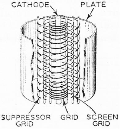
Actual Pentode Grid Structure
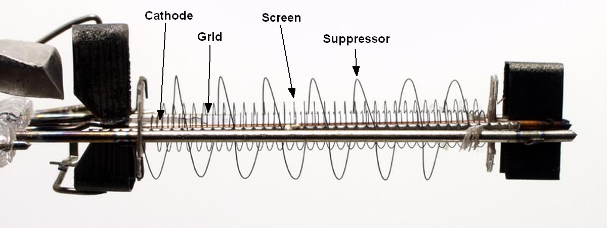
Innermost control grid is wrapped around the cathode, next is the screen grid and outermost is suppressor grid. Note how the control grid and screen grid do not line up with one another. This exposes the screen grid to many more electron impacts and the resulting increase in screen current.
Beam Tetrode Power Tube
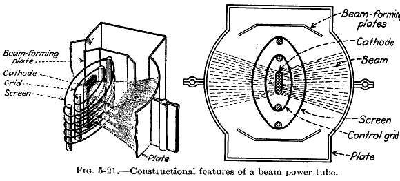
A beam tetrode's control grid and screen grid are precisely aligned to shield the screen from electrons to reduce electron impact and screen current.
Controlling Screen Current
Since true pentodes flow much more screen current than beam tetrodes, amps designed for pentodes like the EL84 and EL34 need to limit screen current to prevent excessive current from melting the screen which can short the tube and blow the screen stopper resistor. A beam tetrode amp can get away with a small low watt screen resistor (some Fender amps have no screen resistor at all) but a true pentode amp needs more protection. A typical pentode screen stopper resistor is 1K and rated for 5 watts. I believe all modern tube amps should have a screen resistor of 470 to 1.5k and 3 to 5 watts to handle extreme, long term overdrive.
Since a screen stopper resistor will restrict the flow of electrons off the screen and cause a buildup of electrons, a screen resistor will accelerate screen voltage drop and increase distortion and so quicken the power amp's transition from clean to distortion. Increasing the resistance value of the screen resistor will increase the overdrive screen voltage drop and therefore increase power tube distortion, compression and sustain. But as with most things in amplifier electronics there is a sweet spot. Too much screen grid resistance will start to sound funky. Time has tested and proved the 470 to 1.5K screen resistor value.
Since screen current affects the tube's operating point along the transfer curve and changes the shape and slope of the tube's transfer curve it has more effect on power tube overdrive tone than grid current.
Personally I like screen voltage fluctuation because of its transfer curve morphing distortion so I recommend larger ohm value resistors that enhance screen voltage drop and safely limit overdrive screen current. My suggested screen stopper resistor values are (one screen stopper per tube) :
6V6: 1k (3 watt or higher)
6L6, 5881: 1k 5 watt
EL84 (true pentode) 1.5k 3 watt
EL34 (true pentode) 1.5k 5 watt
Feel free to experiment with even larger values such as 2.2k for more distortion, compression and sustain.
Grid Stopper & Screen Resistors Mounted to the Power Tube Sockets
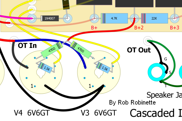
470 ohm 3 watt screen resistors (green) added to my Fender 5E3 Deluxe power tube sockets to control overdrive screen current and screen dissipation. The 1.5K 1/2 watt blue resistors are grid stopper resistors which prevent blocking distortion by slowing the flow of control grid current and the upstream coupling cap's charge time. Screen and grid stopper resistors also help prevent oscillation by forming an RC low pass filter with the tube's Miller capacitance. The low pass filter eliminates high frequencies beyond human hearing which helps prevent oscillation.
The addition of a screen-to-cathode screen capacitor can reduce the chance of oscillation but more importantly it adds a time-variance factor to screen voltage drop and distortion. The capacitor is charged by screen current and acts as an electron reservoir. The cap's charge/discharge cycle can alter the character of pentode and beam tetrode distortion with added complexity. The addition of a screen cap and trying different cap values may be worth experimentation when tuning an amp's power amp overdrive tone.
Increasing screen stopper resistance increases overdrive screen voltage drop and its distortion but makes the voltage changes slower and less dynamic.
Reducing screen resistance reduces the screen voltage drop but accelerates screen voltage recovery making the voltage changes more dynamic.
When tuning an amp's overdrive tone close attention should be paid to the screen grid stopper resistor and screen-to-cathode cap values. Taking the time to experiment with different component values can pay great dividends and help differentiate the voice of your amp from the rest of the pack.
Output Transformer and Voice Coil Flyback Voltage Spikes
When an amp is heavily overdriven severe clipping can turn the guitar signal into a square wave with very abrupt signal voltage rises and falls. The output transformer and speaker voice coils are inductors whose magnetic fields represent stored energy. The stored energy is used to fight abrupt signal voltage changes. The output transformer and voice coils are what cause the points at the corners of the square wave (see scope capture below). When abrupt voltage changes occur the magnetic fields created by the output transformer and voice coil collapse and generate flyback voltage spikes. These spikes are seen as the "corner points" and "shoulder spikes" in the image below. The spikes also add harmonic and intermodulation distortion.
The shoulder spikes are generated when the signal goes from zero to max and max back to zero voltage. The output transformer and voice coil fight these on and off voltage changes with an opposing voltage spike. These corner and shoulder spikes are part of the aggressive, raspy overdrive tone of the Marshall 18 Watt. Its lack of a global negative feedback loop makes the flyback spikes more prominent than in amps with a negative feedback loop. A negative feedback loop would try to "correct" these spike distortions and smooth them out.
Marshall 18 Watt Heavy Overdrive Output
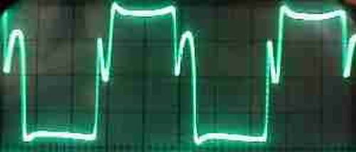
Square wave with flyback voltage "corner points" and "shoulder spikes" generated by the output transformer and speaker voice coil.
Summary
A pentode or beam tetrode circuit with a grid stopper, screen resistor, screen cap and bypassed cathode resistor has a very complex distortion interaction function that can lead to tube overdrive nirvana. All of these components interact with one another during overdrive so tuning all of them to find an overdrive tone and playability sweet spot can be difficult and time consuming.
A pentode interactive distortion circuit is very difficult to simulate using solid state components but I say why bother with a simulation? A tube guitar amplifier's soft, asymmetric clipping, time-varying grid current bias excursion and time-varying screen grid gain shift all combine to make tube overdrive tone more musical than typical solid state distortion.
From the AES journal, May 1973 Tubes versus Transistors: Is There An Audible Difference?
Vacuum-tube amplifiers differ from transistor and operational amplifiers (op amps) because they can be operated in the overload region without adding objectionable distortion. The combination of the slow rising edge and the open harmonic structure of the overload characteristics form an almost ideal sound- recording compressor. Within the 15-20 dB "safe" overload range, the electrical output of the tube amplifier increases by only 2-4 dB, acting like a limiter. However, since the edge is increasing within this range, the subjective loudness remains uncompressed to the ear. This effect causes tube-amplified signals to have a high apparent level, which is not indicated on a volume indicator (VU meter). Tubes sound louder and have a better signal-to-noise ratio because of this extra subjective headroom that transistor amplifiers do not have. Tubes get punch from their naturally brassy overload characteristics. Since the loud signals can be recorded at higher levels, the softer signals are also louder, so they are not lost in tape hiss and they effectively give the tube sound greater clarity. The feeling of more bass response is directly related to the strong second and third harmonic components, which reinforce the "natural" bass with "synthetic" bass [5]. In the context of a limited dynamic range system like the phonograph, recordings made with vacuum-tube pre-amplifiers will have more apparent level and a greater signal to system noise ratio than recordings made with transistors or operational amplifiers.
So yes, tube guitar amps do sound better than solid state.
By Rob Robinette
References
RCA Corporation, RCA Receiving Tube Manual, RC30.
Merlin Blencowe, Designing Tube Preamps for Guitar and Bass, 2nd Edition.
Morgan Jones, Valve Amplifiers, 4th Edition.
Richard Kuehnel, Circuit Analysis of a Legendary Tube Amplifier: The Fender Bassman 5F6-A, 3rd Edition.
Richard Kuehnel, Vacuum Tube Circuit Design: Guitar Amplifier Preamps, 2nd Edition.
Richard Kuehnel, Vacuum Tube Circuit Design: Guitar Amplifier Power Amps
Robert C. Megantz, Design and Construction of Tube Guitar Amplifiers
Neumann & Irving, Guitar Amplifier Overdrive, A Visual Tour It's fairly technical but it's the only book written specifically about guitar amplifier overdrive. It includes many graphs to help make the material easier to understand.
T.E. Rutt, Vacuum Tube Triode Nonlinearity as Part of The Electric Guitar Sound
A Brief History of High Gain Amps
By Y. Blais
The reason it is the way it is goes back to the "origins of high-gain." We have to go back all the way to the 1950's Fender tweed Bassman (5F6A). It combined a bunch of textbook circuits: a pair of input channels (because a 12AY7 has 2 triodes and because multiple inputs were popular at the time), one a bit brighter than the other one (just a treble cap on that volume knob), followed by a second tube that has a DC coupled cathode follower configuration (also used by Vox in the Top Boost circuit) which was used to drive a very lossey TMB tone stack, then a fancy long tail phase inverter with negative feedback driving the phase inverter's second input (because they were trying to make a loud clean amp), into a pair of 5881 power tubes (loud and clean, per 1950's standard).
Then Marshall copied this circuit in the JTM45, putting a 12AX7 in the first slot and connecting it to a closed back 4X12 cab loaded with Celestions. Then the Bright channel was made even bolder in the "Superlead" configuration (JMP years), with its own cathode resistor (2k7) bypassed by a small 0.68uF cap to boost high-mids, coupled through a smaller .0022uF cap instead of a .022uF. They also put a treble cap on that channel's mixing resistor. That was great, but the amp had to be cranked to ridiculous levels to sound really dirty. They would put treble boosters and the like in front, yet it still wasn't enough.
But modders found that running the Lead channel into the Normal one was the trick. Because of the high-mids boosting and low-cutting of that channel, running it into the Normal channel gives a very mean distortion tone, not unlike boosting with a Treble booster.
Marshall soon caught on and released the 2203/2204 Master Volume (what we commonly refer to as "The JCM800", but it was initially a JMP) which used the cascading trick but through their experimentation decided to make the second triode a "cold clipper": replacing the bypassed 820 ohm cathode resistor with a big unbypassed 10k. If you've ever experimented with a 2203/2204 circuit, you know that keeping the second stage "warm" gives you more overdrive, albeit softer and muddier sounding (good for leads perhaps, but not crunchy enough for heavy riffage).
After that, Marshall experimented with diode clipping and such to get more distortion, but not everyone liked it.
The 2203/2204 circuit works really well with a booster pedal in front (Tubescreamer or Super Overdrive for example), so the next logical step was: let's add a gain stage before it, make the booster built-in using a tube. So what do you get? A first stage that is usually configured for very high gain (typically a 220k plate load) focused mostly on the mids and highs (1uF or less bypass cap, 2.2-4.7nF coupling cap, a series resistors bypassed with a cap before the gain control as a "treble peaker", etc), a second stage that is very similar to the 2203/2204's first stage, and a cold-biased third stage that doesn't add much gain but distorts in a more pleasing way than diodes (Soldano used 39k for the cathode resistor instead of 10k because with that extra gain stage in front, 10k was a bit "too much").
Interestingly, Soldano also added a DC coupled cathode follower to drive an FX loop before the tone stack, which means you get TWO cathode followers, and DC coupled cathode followers have a pleasing compression effect that can smooth things out. That's a big part of the Soldano sound that neither Mesa Boogie (with the Dual Rectifier) or Peavey (with the 5150) replicated.
Others got more gain from the 2203/2204 circuit by configuring the fourth stage (the DC coupled Cathode Follower) into a regular anode driven gain stage (this results in more loss in the tone stack and a different response, but it does give more distortion).
And then you get the Peavey 5150 going all out and combining both the extra "booster" gain stage with the plate driven tone stack for massive amounts of distortion.
So as you can see, all these circuits are just simple ways of getting more gain from a "JCM800" circuit (which itself was just a Plexi, aka a modified tweed Bassman, running the Lead channel into the Normal and adding a Master Volume). There are some nuances though: for example the Dual Rectifier mostly took the Soldano SLO circuit with that 39k third cold clipper stage but moved the FX loop to after the tone stack (using an AC coupled cathode follower which doesn't have as much color) AND disconnected the negative feedback circuit while replacing the Presence circuit with a simple treble attenuation control (this explains its massive bass-heavy sound). Other amps replaced the classic tone stack with a Baxandall stack (less interactive, allows treble boost AND cut).
If you want to see a truly different circuit, check out Mesa's Mark series. They look very complicated because of all the switching options, but if you go back to the Mark IIC+ and ignore all the complicated stuff, you mostly get this: a blackface Fender (say a 60's Twin) with the reverb circuit replaced by a gain boost circuit. Look at it, you'll see it: first stage drives a tone stack via the plate, then is followed by a recovery stage (textbook Fender blackface), then you get the 3M3 resistor which is typically used to attenuate the signal to mix it with the reverb, but instead of a reverb circuit you get the "Lead" circuit which is a pair of triodes (aka one 12AX7) configured for high gain. What you get is basically trying to replicate a cranked to hell Fender: lots of distortion AFTER the tone stack instead of before it. Also the interesting thing is you get a bit of clean sound mixed in with the extra distortion (what makes it through the 3M3 resistor). The resulting sound however is very mid-heavy, hence the graphic EQ, which is a much more powerful tone shaper than the classic TMB tone stack (especially this one, which runs on much higher voltage than a pedal). This gives you a lot of power, the early tone stack can be used to shape the distortion (crank Treble, cut Bass for a very tight aggressive sound, go more moderate for that "fusion" lead sound), then the graphic EQ lets you do the final shaping. Boosting the lows late will not muddy up the distortion, that's how it can sound so massive while tight (the "Simulclass" power amp where 2 of the tubes run in Triode mode help here too).
I've drawn up schematics and layouts for a dozen high gain amp ideas over the years, but it seems I always go back to the 2203/2204 circuit. I find it more flexible to use boost pedals in front of that circuit because I get more variety depending on which pedal I use, and the classic JCM800 crunch is always there waiting for me, and I don't "need" a clean channel because it cleans up well with the guitar's volume. Also, this saves me adding a fourth preamp tube, and makes it easier to keep hiss and hum down (most 5-stage amps will use DC filaments on at least the 1st tube).
But if I was to build a high gain amp, I'd do it this way: V1a would be a bypassable "booster" stage (like the first stage on a Soldano), V1b would be the usual JCM800 first stage (100k, 2k7/0.68uF, .0022uF coupling, 470k/470pF treble peaker, 1nF treble cap on gain) and V2a would be the JCM800 cold clipper (unbypassed 10k cathode). V2b would be the warm biased stage (100k, 820R unbypassed) usually driving the Cathode Follower but instead it would drive a MOSFET follower (saves me a 4th preamp tube just for that one gain stage), from there it would be textbook JCM800 (but with a 56k slope resistor in the tone stack and a 330pF treble cap and 47nF bass cap). Marshall themselves used a similar trick in the JCM1 (V2a drives a MOSFET follower driving the tone stack, V2b is a Cathodyne Inverter, that's how they get a JCM800 preamp with just 2 tubes)
I guess what I'm saying is that this typical high gain amp configuration was not developed through thoroughly directed research, but mostly through years of trying to get more and more gain from the classic "Plexi" (but really tweed Bassman) circuit.
By Y. Blais
Take a look at my How Tube Amps Work, How the 5E3 Works and How the AB763 Deluxe Reverb Works webpages for more tube amp info.
References
RCA Corporation, RCA Receiving Tube Manual, RC30.
Merlin Blencowe, Designing Tube Preamps for Guitar and Bass, 2nd Edition.
Merlin Blencowe, Designing High-Fidelity Tube Preamps
Morgan Jones, Valve Amplifiers, 4th Edition.
Richard Kuehnel, Circuit Analysis of a Legendary Tube Amplifier: The Fender Bassman 5F6-A, 3rd Edition.
Richard Kuehnel, Vacuum Tube Circuit Design: Guitar Amplifier Preamps, 2nd Edition.
Richard Kuehnel, Vacuum Tube Circuit Design: Guitar Amplifier Power Amps
Robert C. Megantz, Design and Construction of Tube Guitar Amplifiers
Neumann & Irving, Guitar Amplifier Overdrive, A Visual Tour It's fairly technical but it's the only book written specifically about guitar amplifier overdrive. It includes many graphs to help make the material easier to understand.
T.E. Rutt, Vacuum Tube Triode Nonlinearity as Part of The Electric Guitar Sound
[ How the 5E3 Deluxe Works ] [ Deluxe Models ] [ DRRI & 68 CDR Mods ] [ Amp Troubleshooting ] [ My 5E3 Build ] [ Spice Analysis ] [ The Trainwreck Pages ] [ Fender Input Jacks ] [ B9A Prototype Boards ]