Photo by Rob Robinette.
How Tubes Work
By Rob Robinette
Have comments or corrections? Email rob at: robinette at comcast dot net
WARNING: A tube amplifier chassis contains lethal high voltage even when unplugged--sometimes over 700 volts AC and 500 volts DC. If you have not been trained to work with high voltage then have an amp technician service your amp. Never touch the amplifier chassis with one hand while probing with the other hand because a lethal shock can run between your arms through your heart. Use just one hand when working on a powered amp. See more tube amplifier safety info here.
Let's start at the beginning with the tube's glass shell which holds a vacuum. A vacuum is needed to keep the electrodes from burning or oxidizing--the same reason a vacuum is needed in a light bulb (a light bulb is actually a single electrode tube!). The vacuum also keeps the electrons in the tube from colliding with air molecules which would generate noise.
Russian 6N3C beam tetrode power tubes in my 1972 Fender silverface Bandmaster Reverb. The cathode is glowing hot. You can see the control grid and screen grid wires running in front of the cathode. The little UFO looking thing near the base of the tube is the getter halo that held the getter flash during manufacturing. Photo by Rob Robinette
A quick note about 'Conventional Current Flow.' In electric circuits negatively charged electrons actually flow from the negative '-' battery terminal to the positive '+' terminal. That's right, the electricity in your car flows from the battery's - terminal through the ground wire, through the car's body, through the radio's ground wire to the radio and then through the positive power wire back to the battery. The problem is that Benjamin Franklin guessed wrong on the direction of electrical flow so conventionally we think of electricity as flowing from + to -. With tubes it helps to actually consider how the electrons are really moving in order to understand them.
Edison discovered while working on the light bulb that if you put a wire in a vacuum tube and heat the wire (light bulb filament) electrons would "boil off" into the vacuum. The kinetic energy of the hot, vibrating electrons in the hot wire actually knock electrons off the wire into the tube vacuum. He also discovered that since opposite electrical charges are attracted to one another he could put a positively charged 'plate' inside the tube to collect the free electrons and create a current from the hot filament (cathode) across the gap to the plate. This is the 'Edison Effect,' which acts as a one-way electronic valve--heat the filament and electrons flow, remove the heat and the flow stops. It's a one-way valve because the plate is not heated so electrons can't flow from the plate to the filament. This is why vacuum tubes are referred to as 'valves.'
Later someone discovered you could put an electrically charged metal screen, or 'grid,' between the cathode and plate to block the electron flow. Because like charges repel, a negative charge on the grid (lots of excess electrons on the grid) repels the negatively charged free electrons trying to flow from the cathode through the grid to the plate. But a positive charge on the grid (scarcity of electrons) allows the free electrons to pass through the grid. If you fluctuate the electric charge on the 'control grid' you fluctuate the current flow between the cathode and plate. This effect is used as a signal amplifier by applying a low level guitar signal to the grid which controls the much larger flow of free electrons between the cathode and plate (the plate is also called the anode--next time you want to insult someone call them an 'anode' :D ). With 400 volts on the plate the electrons move at about 24 million miles per hour from cathode to plate (yea, wow).
In the Champ amp tube V1A is the first preamp and V1B functions as the output stage driver. V1A and V1B are triodes because they have three electrodes, a grid, plate and cathode. Some simple tubes like half-wave rectifiers have only a cathode and plate and are called diodes (two electrodes). A tube with five electrodes is called a pentode. The Champ's power tube, V2 is a tetrode with four electrodes. I guess you could say a light bulb is a uniode with just one electrode ;)
Three Minute Long "How Tubes Work" Video
This is a great little video to help you visualize what happens inside a tube and how it's used as an amplifier.
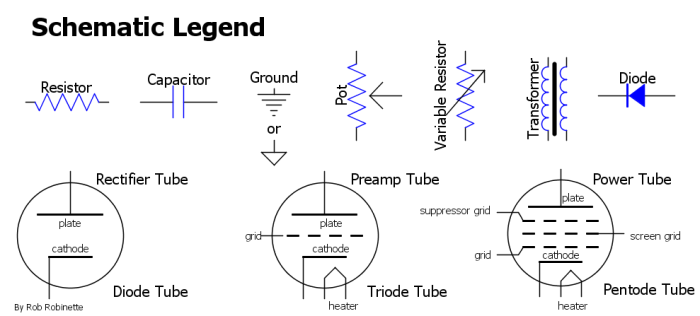
Common amp electronic component symbols.
Standard Vacuum Tube Preamp Stage
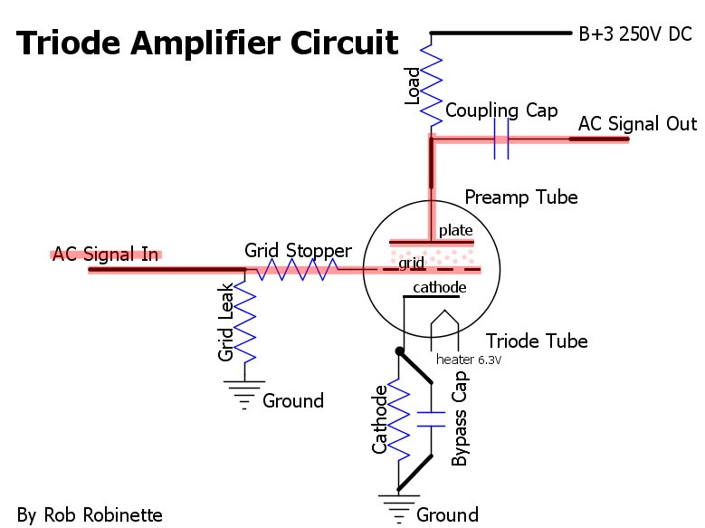
Guitar signal shown in pink enters the tube on the left at "AC Signal In." The guitar signal flows through the Grid Stopper resistor to the tube's Grid, then out the tube's Plate, through the Coupling capacitor and on to the next amp circuit. The Grid Leak resistor bleeds off unwanted captured electrons (grid current) to keep the grid at zero volts DC. The optional Grid Stopper resistor filters high frequencies above human hearing. The Cathode resistor generates the bias voltage between the cathode and grid. The optional Bypass capacitor boosts gain by acting as an electron reservoir. The tube's Cathode is the source of electrons. The Grid controls the flow of electrons through the tube. The Plate is charged with high voltage DC to pull electrons from the cathode, through the grid to the Plate. The Load resistor transforms the circuit from a current amplifier to a voltage amplifier. The Coupling cap keeps the Plate's high voltage DC from flowing downstream but allows the guitar AC signal voltage to pass. This tube is a 'triode' which means it has three electrodes: the grid, plate and cathode.
Get to know the Standard Vacuum Tube Preamp Stage shown above because you'll see several of them in just about every tube amp. Notice in the diagram above we have both a filament heater and a cathode. In most tubes the cathode is indirectly heated by a filament wire. The power transformer sends 6.3 volts of alternating current (AC) through twisted green heater wires to power the Champ's pilot light and the V1 and V2 filament heaters. The rectifier tube is different as its cathode is directly heated by 5 volts AC from the power transformer's yellow twisted wires. The wires are twisted to minimize the electronic noise generated by the AC flowing through the wires.
Referring to the above Standard Vacuum Tube Preamp diagram again, the guitar audio signal enters on the left at 'AC Signal In.' The signal flows to the tube's 'control grid' shown as the dashed line inside the tube. As the audio signal voltage fluctuates, the electrical charge of the grid fluctuates too. As the grid voltage fluctuates its blocking power fluctuates so the electron flow between the hot cathode and the plate fluctuates to the guitar signal. The voltage fluctuations on the plate are the amplified guitar signal. When the grid goes negative (more electrons) the extra electrons on the grid repel the electrons that are trying to get through the grid to the plate because like electrical charges repel. When the control grid voltage goes positive (fewer electrons) more current is allowed to pass through the grid from cathode to plate.
At this point the tube is acting as a current amplifier. Small voltage changes on the tube's control grid are amplified into large current changes on the tube's plate. Remember voltage is 'electronic pressure' and current is the amount of electrons flowing. We will discuss later how the tube's load resistor transforms the circuit from a current amplifier to a voltage amplifier.
Grid leak resistors 'leak' off unwanted DC voltage created when free electrons from the cathode hit the grid. Ridding the grid of these electrons prevents a grid voltage buildup which would affect the grid-to-cathode bias voltage.
An important concept to understand with tube electronics is that the plate brings in high voltage DC to power the tube and simultaneously carries the amplified AC audio signal out. The AC audio signal 'rides on top' of the DC. This is called 'DC offset.'
Plate current is really just variable DC. Electrons flowing from cathode to plate move only in one direction which is the definition of DC. But we consider the fluctuations of DC voltage an AC signal "riding on top of a DC voltage". If you remove the DC component with a transformer or coupling cap you end up with a true AC signal.
AC Audio Signal With DC Offset
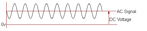
The AC audio signal rides on top of the tube's high voltage DC.
How the Load Resistor Works
Once again referring to the Vacuum Tube Preamp diagram above the load resistor is shown connected to the tube's plate. The load resistor changes the amplifier circuit from a current amplifier to a voltage amplifier. The load resistor allows a small flow of current from the tube's plate to make a large change in voltage thus creating a voltage amplifier. The load resistor restricts the flow from the 250v DC power supply to the tube's plate. When the tube flows negatively charged electrons to the positively charged plate the voltage drops across the load resistor and between the load resistor and plate. If you slow the flow of electrons from cathode to plate the voltage drop across the load resistor will decrease causing a voltage rise on the plate. Stop the flow completely and the voltage on both sides of the load resistor will equalize at 250 volts. If there's no current flowing there will be no voltage drop across the load resistor.
One way to describe how a tube is used as a voltage amplifier is with a water hose analogy. Think of the high voltage power as water faucet pressure and the wire running from the power supply to the tube plate as a water hose. You can simulate the load resistor by clamping the hose partially shut. Water flows through the clamp but at reduced pressure. The water pressure is the voltage, the water flow is the current and the clamp is the load resistor resistance.
You have high pressure from the faucet and when water is flowing the clamp reduces the pressure beyond the clamp. There is a pressure drop across the hose clamp. Now put your thumb over the end of the hose--your thumb simulates the preamp tube's control grid. Close off the flow with your finger and you have no water flowing and the water pressure will rise and equalize on both sides of the clamp so there's no pressure drop across the clamp. This simulates the control grid stopping the electron flow from the cathode to the plate--no flow = no voltage drop across the load resistor.
Now allow some water to flow by releasing thumb pressure and the pressure will rapidly drop in the hose between your finger and the clamp. This simulates the control grid allowing electrons to flow to the plate. Add more thumb pressure to decrease the water spray and the hose pressure increases, allow more to flow by your thumb and the pressure drops. The partially clamped hose causes more pressure drop when small amounts of water are released. Without the restriction of the clamp much more water must be released to get the same pressure drop. The load resistor causes much more voltage drop when small amounts of current are released by the control grid. Without the load resistor much more current would have to flow between the cathode and plate to get the same voltage drop.
The tube's control grid 'releases pressure' (lowers voltage) by flowing negatively charged electrons onto the positively charged plate. The electrons are pulled by the power supply toward the load resistor but they stack up when they hit the load resistor--this is what causes the voltage drop across the plate resistor--there's more electrons on one side of the resistor. More stacked up electrons = lower voltage on the plate. When the control grid slows the flow of electrons the voltage rises on the plate because the power supply is constantly pulling electrons through the plate resistor (fewer electrons = higher voltage). These voltage fluctuations on the plate are the amplified guitar audio signal.
Referring once again to the above Standard Vacuum Tube Preamp Stage, the Coupling cap at upper right blocks high voltage DC but allows the AC guitar signal to pass through to the next amplifier stage.
Triode Vacuum Tubes
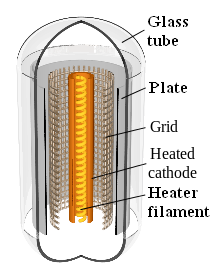
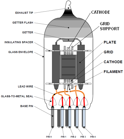
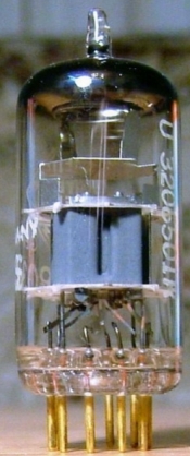
Single triode vacuum tube on the left, note its tubular structure. The 12AX7 middle and right is a dual triode tube--two tubes in one. Pin 1 connects to the Plate (output), Pin 2 the Grid (input), Pin 3 the Cathode (source of electrons). Pin 6 connects to the 'B' triode's Plate, Pin 7 the Grid, Pin 8 the Cathode. Pins 4, 5 & 9 connect to the heater filaments. The halo like 'Getter' at the top of the tube held the material used to create the 'Getter Flash' (mirror-like substance on top inside of tube). The Getter Flash absorbs gas molecules to maintain the tube's vacuum. If the Getter Flash turns from silver to ash white you know the tube has been contaminated with too much oxygen from a vacuum leak.
Dual Triode Tube
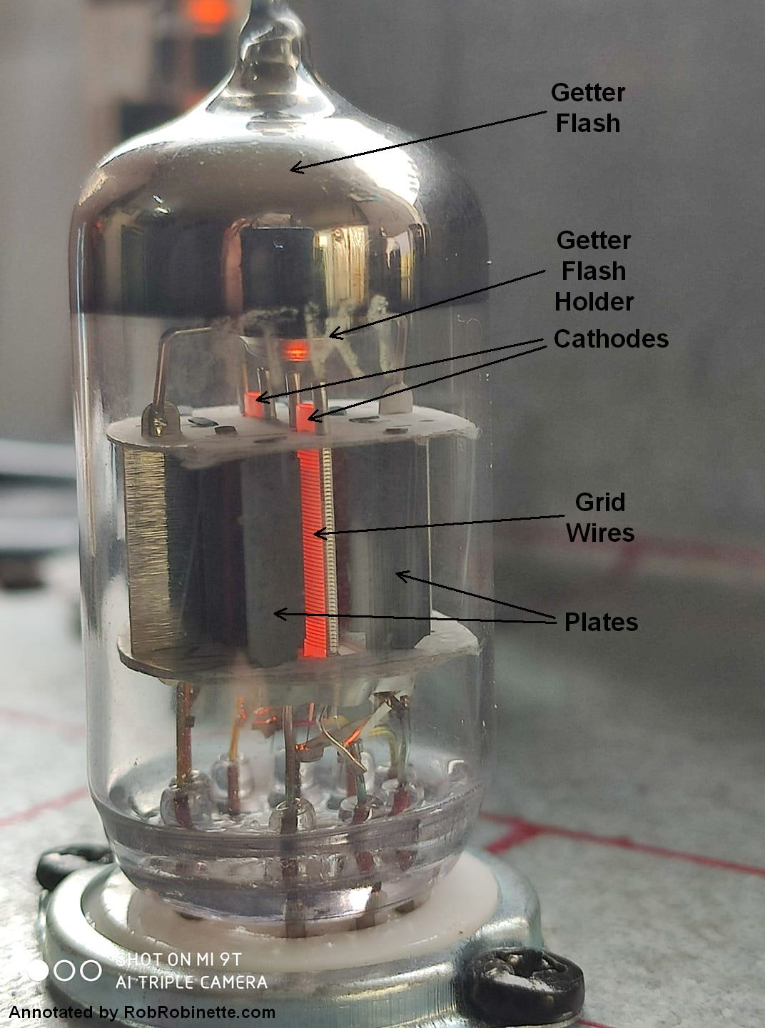
The glowing hot tubes are the dual cathodes (this is a dual triode design). The horizontal lines across the cathode are the control grid wire. The big gray metal pieces in front of and behind the cathodes are the plates that collect the electrons given off by the cathodes. The heater filaments are run up inside the hollow cathode. Photo by Brian Proulx.
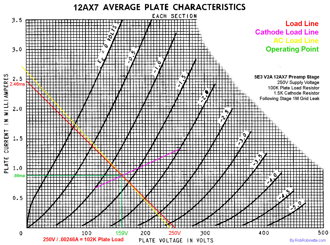
This is a 12AX7 plate characteristic chart. Notice the curved grid voltage lines? They are curved so they are nonlinear and always induce nonlinear distortion which also causes harmonic and intermodulation distortion. This is why tube amps tend to sound "warm". The distortion fattens up the tone of anything being amplified by a tube circuit. Don't confuse distortion with noise. The right kind of distortion can make guitar or music in general sound better.
6V6GT Beam Tetrode Power Tube
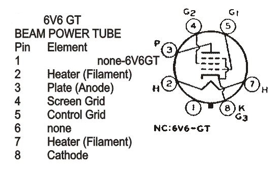
Note pin 8 is connected to the cathode (K) and the beam confining plates (g3). H=heater, P=plate, G=grid. Pin 1 and Pin 6 are not connected to anything. This diagram is from the 6V6GT tube datasheet.
The 6V6GT is known as a beam tetrode but in reality it has five electrodes so it should be called a beam pentode: cathode, plate, control grid (g1), screen grid (g2) and beam confining electrode (g3). It was called a tetrode to avoid patent infringement with the pentode. The screen grid provides a constant, positive voltage to strongly attract electrons from the cathode. It also isolates the control grid from the plate which reduces parasitic capacitance between them which increases the tube's gain and stability. Some amps have a switch to run a tetrode or pentode tube in lower power 'triode mode' by tying the screen grid and plate together which allows the screen grid's voltage to fluctuate with the plate.
6V6GT Beam Tetrode
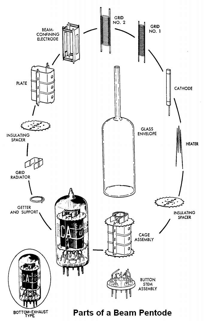
A beam tetrode's "beam confining electrode" (top left) is tied to the cathode and directs electron flow into a beam and onto the plate. The beam confining electrode is the tube's fifth electrode. The heater wires are shoved up inside the cathode, which is placed inside Grid NO.1 (control grid), which is placed inside Grid NO. 2 (screen), which is placed inside the beam confining electrode, which is placed inside the plate.
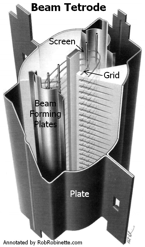
The aligned grid and screen shields the screen and lowers screen current.
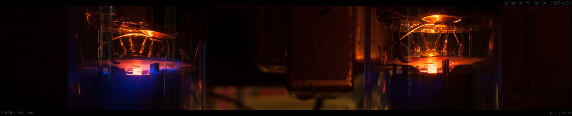
6L6GC Beam Tetrode Power Tube
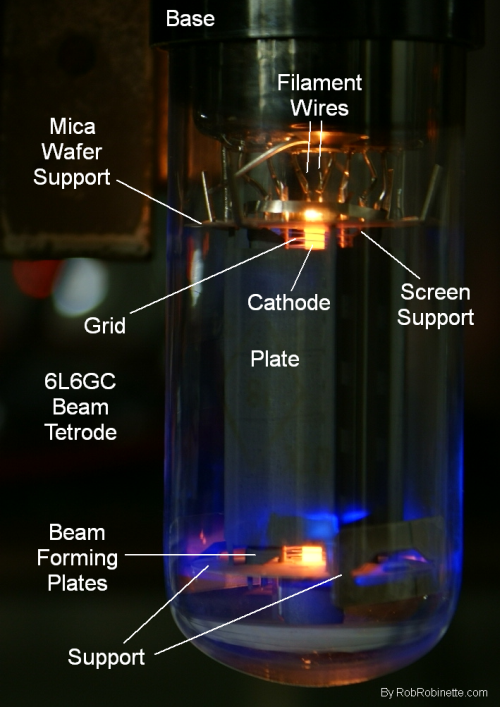
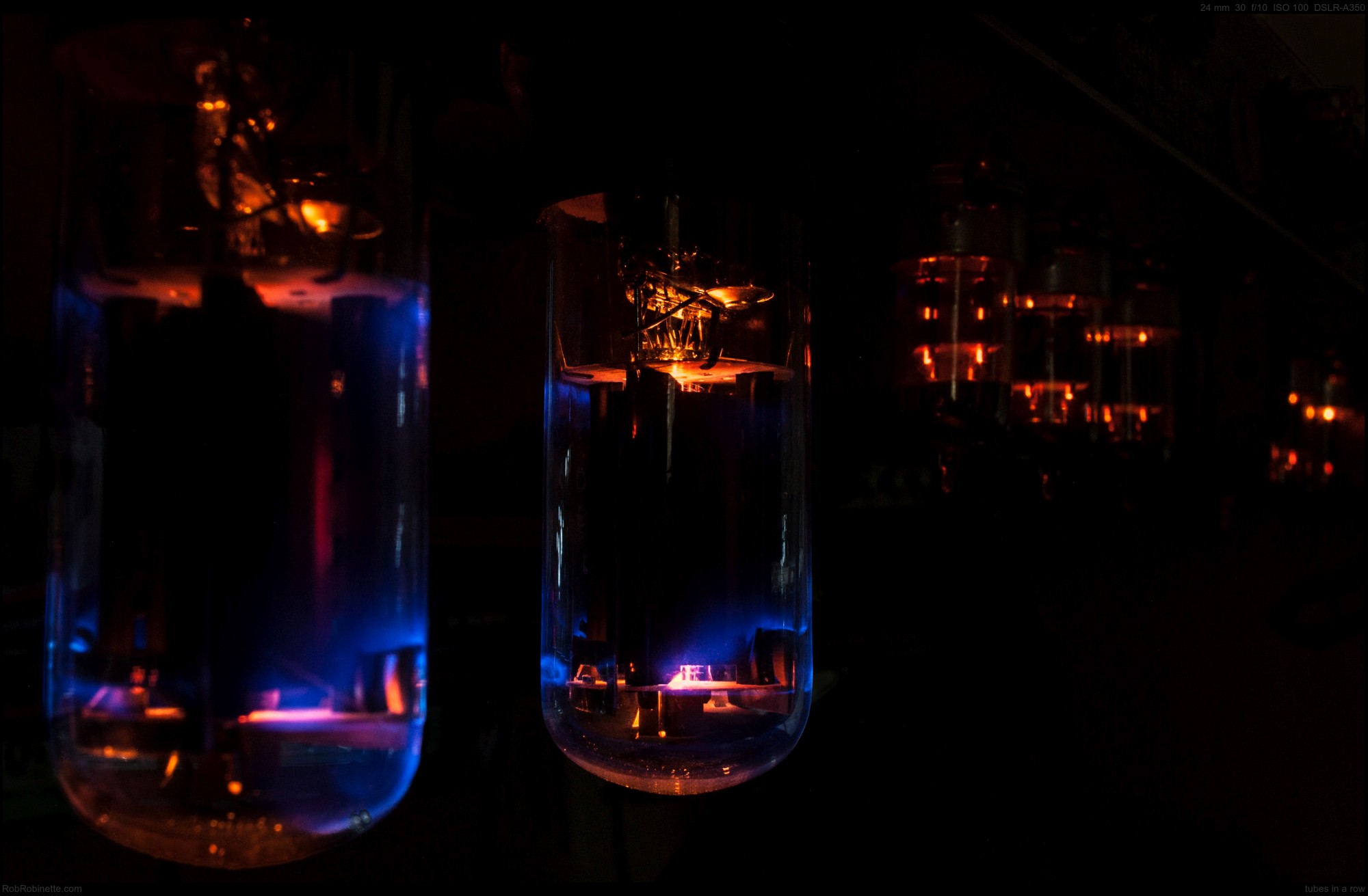
The cool blue glow is caused by electrons striking gas molecules.
Non-beam power tubes such as the EL34 and EL37 don't have a beam confining electrode but have a suppressor grid as grid 3 (g3) which is tied directly to the cathode and keeps high speed electrons from bouncing off the plate upon impact.
EL37 True Pentode Cathode and Grids
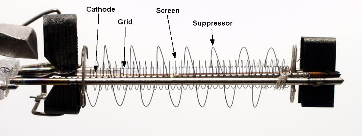
In this true pentode the Suppressor Grid (g3) replaces the beam tetrode's Beam Confining Electrode (also called g3).
Take a look at this page with excellent detail shots of an EL37 true pentode's insides which clearly shows the control, screen and suppressor grids.
So to review, the filament heats the cathode, the cathode gives off electrons, the plate and screen attract the free electrons but the grid controls the flow--the control grid is the valve that controls the flow of electrons through the tube. Place a guitar signal voltage on the control grid and the guitar signal will control the flow and the tube's output will be the amplified guitar signal.
Back to First Preamp Stage.
See How to Draw Tube Load Lines for more insight into how tubes work.
See Tube Guitar Amplifier Overdrive for specific information on how overdrive distortion is created.
The Rectifier Tube
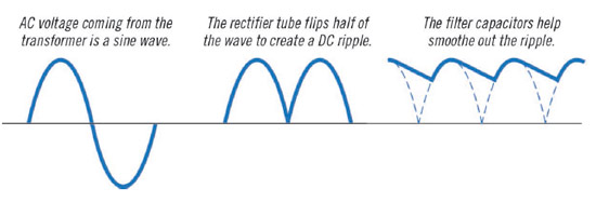
The rectifier tube is a one-way valve that combined with the power transformer acts as an electron pump to convert 325 volts RMS AC into 360 volts DC. This high voltage AC from the transformer is often called HT (high tension) voltage. Note that when you measure between ground and either of the rectifier's AC input wires you'll see 325 AC volts, but if you measure between the two AC input wires you'll see 650 AC volts. An amplifier's rectifier pulls electrons out of the amp circuit to create positive voltage (electron scarcity = positive voltage). V3 is different from the preamp and power tubes in that It has two plates, two cathodes, no grid and its heater filaments are directly connected to the cathode to keep the heater-to-cathode voltage low.
325 volts of alternating current (AC) from the power transformer is connected to the rectifier pins 4 and 6 which connect to the two plates. As the positive half of the AC wave (+325V) charges pin 4's plate positively, pin 6's plate is charged negatively. The pin 4 plate's positive charge attracts electron flow from the cathode generating a positive DC current on the wire attached to the cathode's pin 8 (pulling negatively charged electrons out of the B+ wire connected to pin 8 creates a positive voltage on the wire). Nothing happens to the negatively charged pin 6 plate.
Then as the negative half of the AC wave enters the tube (-325v), pin 6's plate is charged positively and attracts electron flow from the cathode while pin 4's plate is charged negatively and does nothing. Therefore both halves of the AC wave are converted to DC which makes V3's 5Y3GT tube a 'full wave' rectifier.
Rectifier Tubes
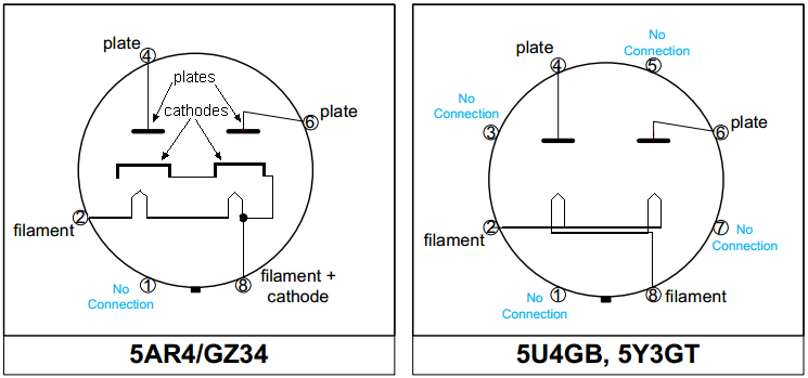
High voltage AC flows onto the plates connected to pins 4 & 6. High voltage DC current flows from the cathode out pin 8. Note the 5Y3GT on the right has a directly heated combined cathode/filament where the GZ34 on the left has a separate cathode and filament that are electrically connected.
Both positive and negative voltage is used to create pulsing DC in a full wave rectifier like the 5Y3 and GZ34.
Because the cathodes are directly heated by the power transformer's 5v AC supply the cathode has both 5v AC and high voltage B+ DC on it at the same time. This is why the 5v heater supply doesn't have a center tap like the 6.3v supply--the B+ DC voltage would be shorted to ground through a center tap. This 5v AC is on the B+ output wire but is filtered out at the first filter capacitor.
Most fixed bias amplifiers use a single diode to rectify the 50v DC fixed bias voltage. The single diode functions as a half wave rectifier and generates a very lumpy DC voltage that must be filtered by a resistor and relatively large capacitor (RC filter).
5Y3GT Rectifier
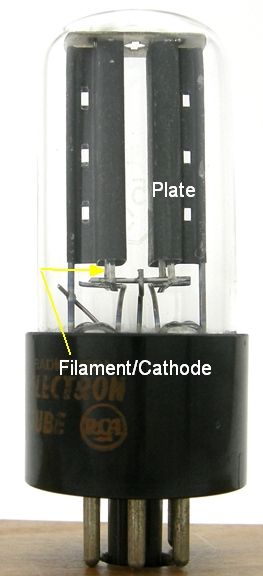
The cathode and filament are combined.
The Internals of the JJ GZ34S Rectifier Tube
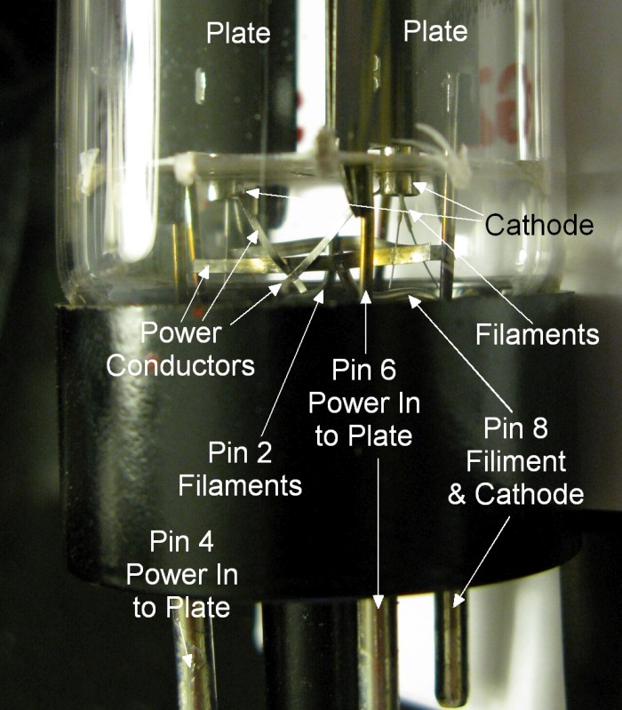
The GZ34S's two big metal plates are hollow in the center so the two cathodes (hollow tubes) will fit up inside them. High voltage AC is brought in from the Power Transformer through Pins 4 and 6 to charge the plates. The fit is tight but the cathode and plate do not touch each other. The hollow cathodes have filament heater wires running their entire length inside them. The hot cathodes emit negatively charged electrons. The free electrons are pulled to the positively charged plates. Notice the thick power conductors that connect both cathodes to the output pin 8. Electrons are pulled through these conductors from the B+ wire attached to pin 8. Removing electrons from the B+ wire creates a positive charge in the wire. Conventionally we think of positive DC power flowing from the cathode and out pin 8 to the circuit board when in reality the electrons are flowing the opposite direction. Photos by Rob Robinette.
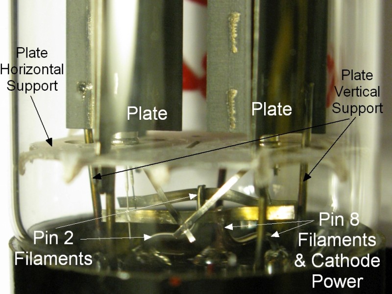
The plate horizontal and vertical supports hold the plates and cathodes in place. The Getter Halo's (below) only function was to hold the 'getter flash' until it was flashed onto the inside of the tube (the silver coating on the top of the tube). This silver coating or "flash" absorbs oxygen molecules to keep the tube's vacuum oxygen free.
JJ GZ34S Rectifier Tube
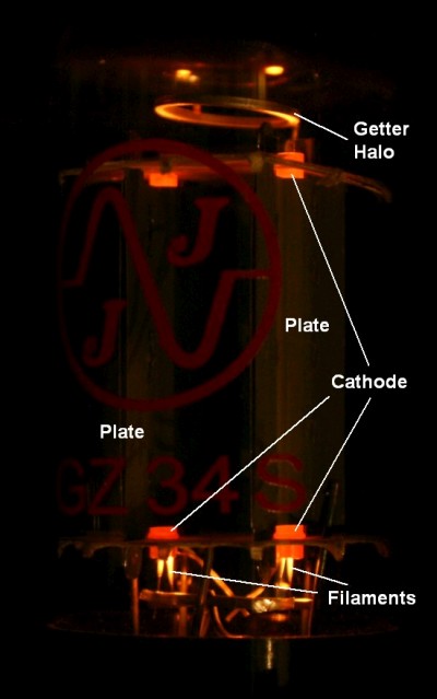
Photos by Rob Robinette.
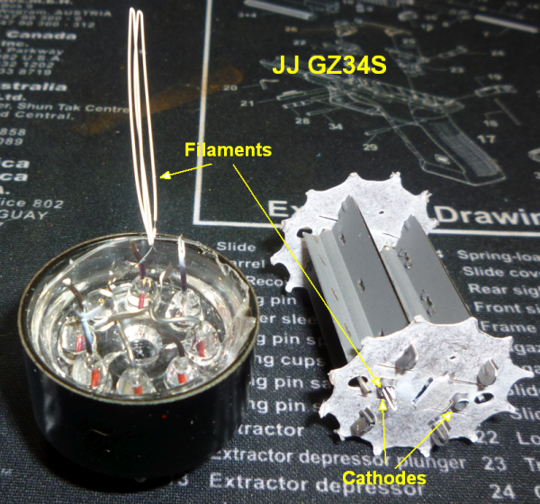
Double folded cathode heater filaments are coated with thin electrical insulation and shoved up inside the hollow cathode.
By Rob Robinette
Suggested follow on reading:
How to Read Tube Amp Schematics It's easier than you think.
How the Fender 5E3 Deluxe tube amplifier works
Deluxe Models from the Woodie to the 68 Custom Deluxe Reverb Reissue.
Fender 5F6A Bassman Information and Modifications
How the Fender blackface AB763 Deluxe Reverb Works
AB763 Model Differences What's the difference between a blackface Vibroverb and Vibrolux?
How the TMB Tone Stack Works It looks like a simple tone circuit but it's not.
How Fender Input Jacks Work Bright, Normal, High, Low: it's an elegant circuit.
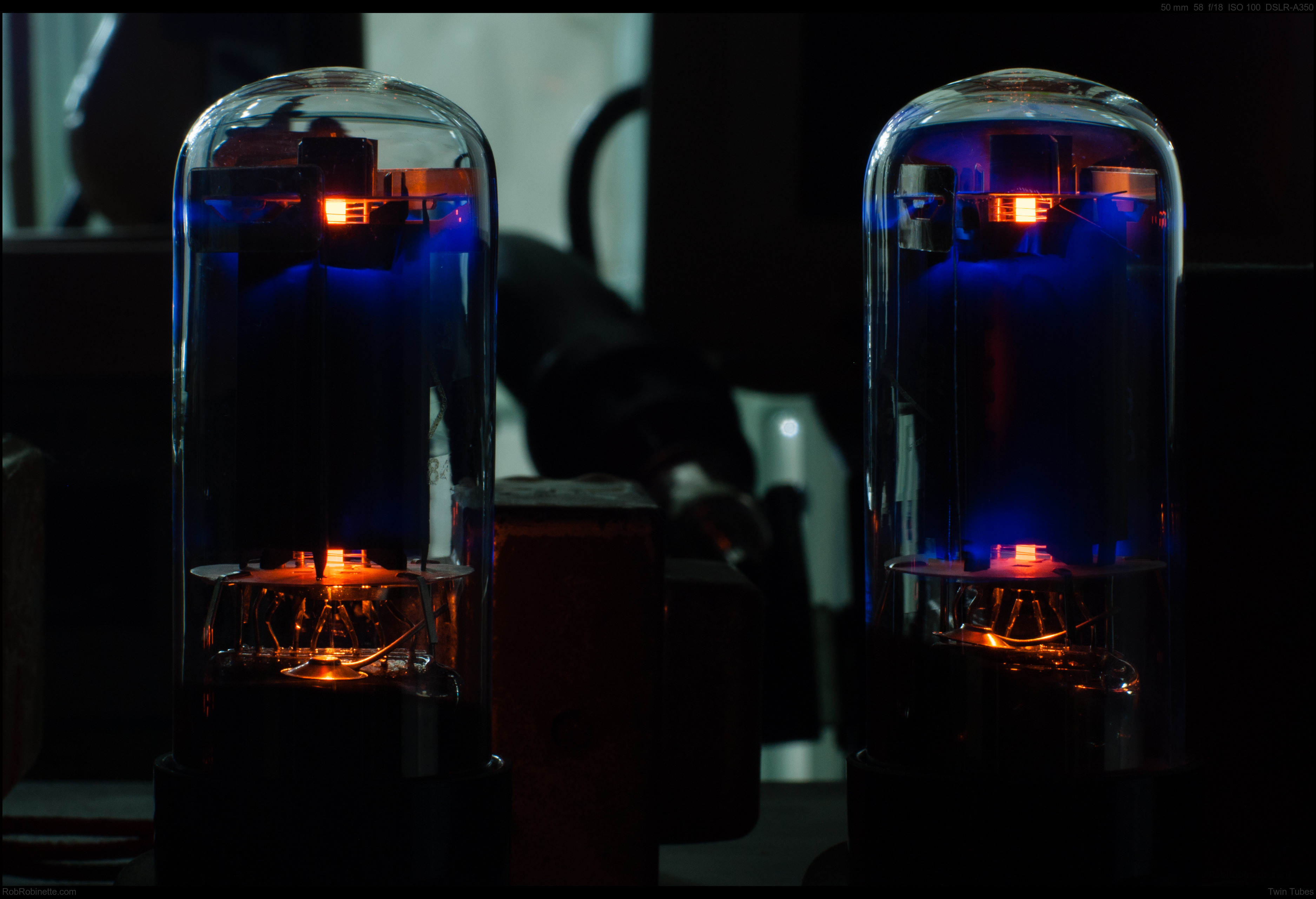
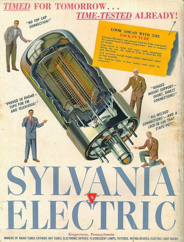
Big Honkin' Tube
References
RCA Corporation, RCA Receiving Tube Manual, RC30.
Merlin Blencowe, Designing Tube Preamps for Guitar and Bass, 2nd Edition.
Merlin Blencowe, Designing High-Fidelity Tube Preamps
Morgan Jones, Valve Amplifiers, 4th Edition.
Richard Kuehnel, Circuit Analysis of a Legendary Tube Amplifier: The Fender Bassman 5F6-A, 3rd Edition.
Richard Kuehnel, Vacuum Tube Circuit Design: Guitar Amplifier Preamps, 2nd Edition.
Richard Kuehnel, Vacuum Tube Circuit Design: Guitar Amplifier Power Amps
Robert C. Megantz, Design and Construction of Tube Guitar Amplifiers
Neumann & Irving, Guitar Amplifier Overdrive, A Visual Tour It's fairly technical but it's the only book written specifically about guitar amplifier overdrive. It includes many graphs to help make the material easier to understand.
T.E. Rutt, Vacuum Tube Triode Nonlinearity as Part of The Electric Guitar Sound
[ How the 5E3 Deluxe Works ] [ Deluxe Models ] [ My 5E3 Build ] [ The Trainwreck Pages ] [ Fender Input Jacks ] [ B9A Prototype Boards ]