How Spring Reverb & Tremolo Works
By Rob Robinette, edited 7/19/2017
Have comments or corrections? Email rob at: robinette at comcast dot net
WARNING: A tube amplifier chassis contains lethal high voltage even when unplugged--sometimes over 700 volts AC and 500 volts DC. If you have not been trained to work with high voltage then have an amp technician service your amp. Never touch the amplifier chassis with one hand while probing with the other hand because a lethal shock can run between your arms through your heart. Use just one hand when working on a powered amp. See more tube amplifier safety info here.
Spring Reverb
Old school spring reverb literally uses the movement of springs to delay and replicate an audio signal. Reverb (short for reverberation) simulates the reflected sound from a room's interior. Spring reverb was invented by Hammond and first used in their organs to liven up the tone in acoustically flat church interiors. Fender licensed the reverb circuit from Hammond and Surf Guitar was born.
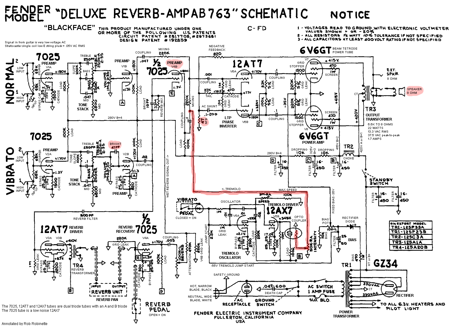
In the AB763 schematic below the guitar audio signal is tapped off to the reverb circuit on the input side of the big 3.3 megaohm Reverb Mix resistor (at upper-center-left). The reverberated wet signal is injected on the other side of the Reverb Mix resistor. The 10pF capacitor in parallel with the Reverb Mix resistor is simply a bright cap. All of the Vibrato channel guitar dry signal must pass through the Reverb Mix resistor or its bright cap.
AB763 Blackface Reverb Circuit
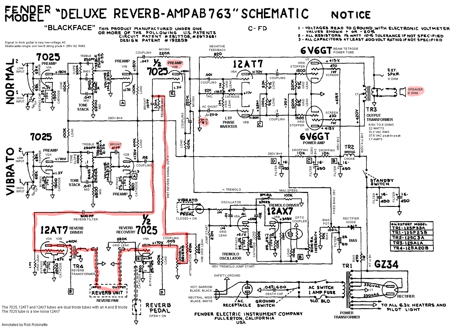
Reverb is at bottom left. Note how the dry signal is tapped off one side of the big 3.3 megaohm Reverb Mix resistor and the wet signal is injected on the other side of the resistor. The 10pF capacitor in parallel with the Reverb Mix resistor is simply a bright cap.
Guitar signal enters at upper left and gets amplified by the Reverb Driver (both stages of a 12AT7 tube in parallel) then flows into the Reverb Transformer which trades high voltage for current. The amplified current is sent to the Reverb Tank's Input Transducer (see tank detail below). The weak 'wet' signal from the tank's Output Transducer is amplified by the Reverb Recovery amp and passed through the Reverb Level control and back to the guitar amplifier.
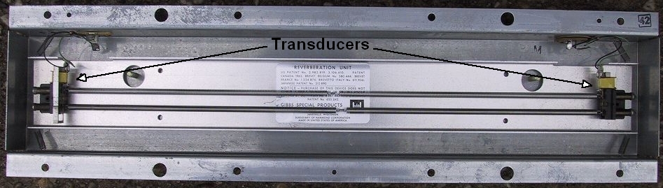
Reverb Tank Detail
Signal enters tank on left and exits on the right. The Input Transducer's input coil moves the transducer magnet which moves the spring which moves the output transducer magnet which generates the reverb signal voltage in the output coil.
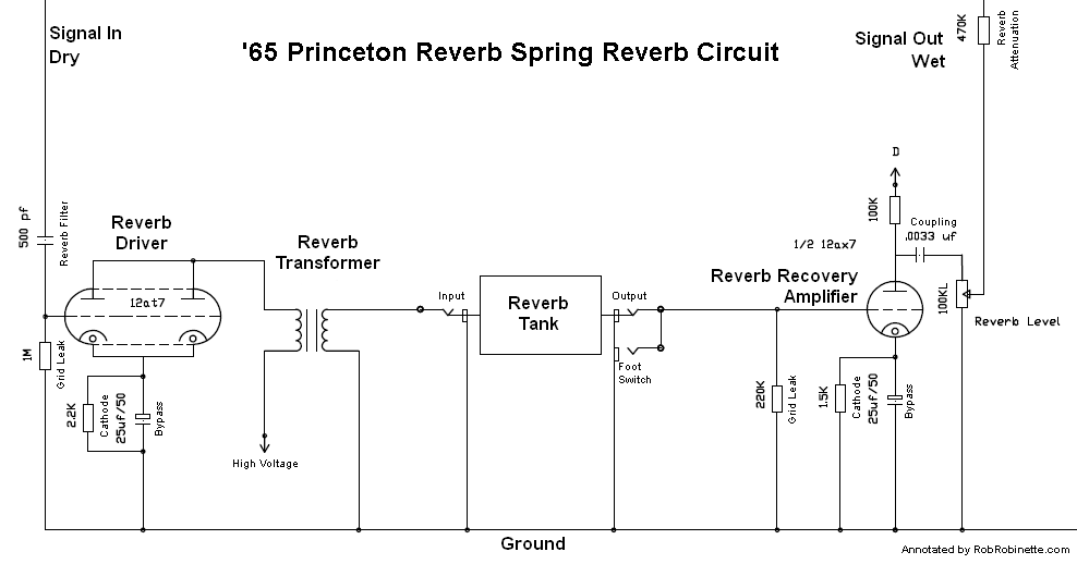
Referring to the 65 Princeton Reverb schematic above, the dry signal enters on the upper left and flows through a 500pF Reverb Filter capacitor which filters out most of the guitar signal's low frequencies. Low frequencies are too long and turn to mud when reverb is applied. The filtered signal then gets boosted by the Reverb Driver amplifier. The Reverb Driver is needed to generate the power to physically move the reverb springs.
After the Reverb Driver the amplified dry guitar signal is then sent through the Reverb Transformer which trades high voltage for current. Amplified current is needed to drive the reverb tank input transducer. The tank's Input Transducer is simply an electromagnet used to move the spring. The amplified audio signal flows through the input transducer's coil which generates a magnetic force. The magnetism generated in the coil is alternately attracted to and repulsed by the transducer's magnet which makes it and the attached springs move.
The transducer movement travels down the Springs and causes movement of the Output Transducer magnet at the other end. The moving magnet's magnetic field cuts through the transducer's output coil which generates the 'wet' reverb signal voltage. In other words, the Input Transducer transforms electrical energy into mechanical movement. The Output Transducer transforms mechanical movement into electrical energy. The weak wet signal generated by the transducer output coil is then amplified by the Reverb Recovery Amplifier and flows through the Reverb Level (volume) pot and back to the amplifier.
Reverb Tank
A reverb tank is simply made up of two transducers connected by two or more springs. The longer the tank the longer the reverb reflections.
The time it takes for the spring movement to travel from input transducer to output is the reverb delay. Multiple springs with slightly different makeup add multiple delays simulating sound reflections from multiple room features. The original spring movement doesn't actually stop at the output transducer. A diminished 'wave' is reflected back along the spring toward the input transducer, bounces off it and returns in weakened form to the output transducer generating multiple diminishing reverb "reflections".
Fender 6G15 1960's Standalone Reverb Unit
Long a favorite of surf guitarists the 1960's Fender 6G15 standalone reverb FX box is as large and as complicated as a tube guitar amplifier. There are kits available for this very cool reverb unit.
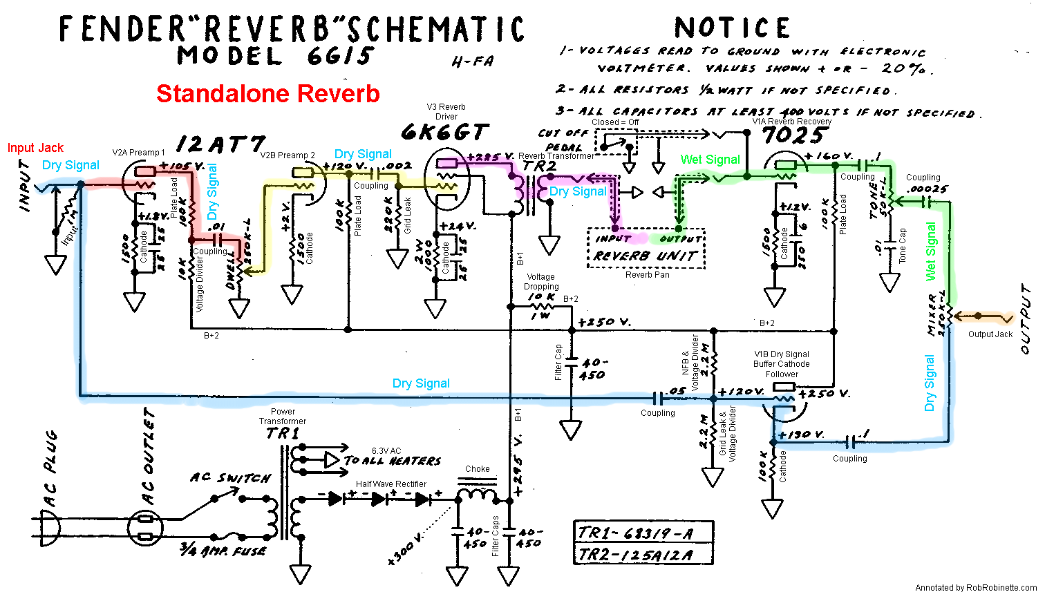
Signal path colors match between the schematic above and layout below to help you follow the layout signal flow. The guitar plugs in to the Input Jack at far left. Preamp 1 (upper left), Preamp 2 and the 6K6GT all boost the dry signal to make it strong enough to jiggle the springs in the Reverb Pan. The signal looses a lot of energy traveling along the springs so the Reverb Recovery triode on the upper right boosts the weak signal coming off the Reverb Pan Output Transducer. The Mixer Pot mixes the bypassed dry signal (blue) and wet signal (green) for output to the amplifier.
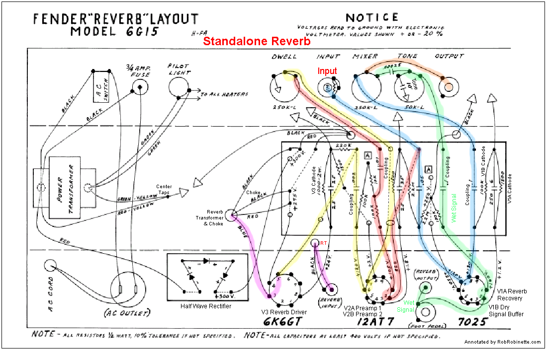
The signal path colors correspond to the colors on the schematic above to help you follow the layout's convoluted signal path.
See the Compact Reverb Add-On Circuit page for more info on reverb circuits.
Tremolo
Tremolo Applied To the Guitar Signal
AB763 blackface style tremolo is the most common tremolo circuit in use. It acts as an automatic wavering volume control which acts directly on the guitar audio signal. This circuit requires two triodes (whole tube), one to generate the oscillation and one to drive a neon light bulb (yes really). This tremolo circuit is also used in the Fender silverface line of amplifiers. Fender sometimes erroneously calls tremolo "vibrato". Real vibrato waivers the signal pitch, not the volume like tremolo.
AB763 Blackface Signal Tremolo Circuit
Tremolo circuit is at bottom center. Note how the tremolo oscillation is inserted into the guitar audio path right before the Vibrato channel's 220k Mixing resistor.
Silverface amp tremolo circuit.
In the Signal Tremolo Circuit schematic below the triode on the left is the Oscillator and its plate (output) is connected to its grid (input) through three oscillator caps. Each oscillator cap is connected to ground through a resistor forming three RC (resistor-capacitor) pairs. Plate voltage charges the oscillator caps and the resistors drain the charge to ground. The time it takes to drain the cap voltage through the resistors causes a delay. Each cap and resistors' delay shift the phase of the oscillation by 60 degrees for a total shift of 180 degrees.
The .02uF oscillator cap closest to the plate is connected to ground through a 3 megaohm variable resistor (Speed pot) and 100k Max Speed resistor. The Speed control alters the resistance in the first RC pair which changes the capacitor discharge time which changes the oscillation frequency (more resistance = slower discharge = slower tremolo). The 100k Max Speed resistor controls the maximum oscillation frequency you can dial in using the Speed control. A lower Max Speed resistor allows a faster maximum tremolo (less resistance = quicker discharge = faster tremolo).
When the delayed, 180 degree out of phase tremolo signal hits the oscillator grid it causes the signal to reverse and the signal coming off the plate never catches up so the oscillation is self sustained. The oscillation signal runs in a circle from plate to grid and grid to plate.
Signal Tremolo Circuit
The oscillator on the left and the tremolo driver is on the right.
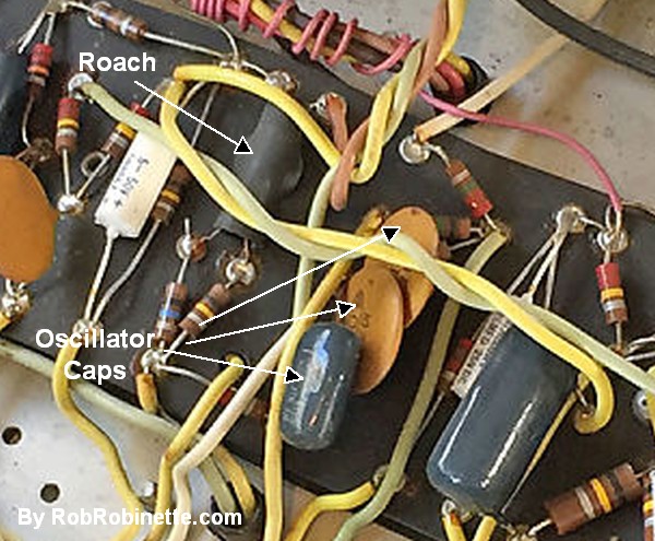
The tremolo signal on the oscillator plate flows to the grid of the triode on the right, the Tremolo Driver. It amplifies the tremolo signal to drive a neon light bulb located inside the "roach," or Opto-Coupler [We could call the neon bulb V10 because it is a single electrode tube ;) ] . The oscillating current from the driver tube plate runs through the neon light bulb causing it to oscillate in brightness. A Light Dependent Resistor or LDR is packaged with the light bulb inside the roach so the neon bulb shines directly on the LDR. As the brightness of the neon bulb changes, the resistance of the light dependent resistor changes with it. The brighter the bulb, the lower the LDR's resistance. The guitar audio signal is connected to the LDR so that when its resistance drops the guitar audio signal is sent to ground which lowers the amp's output volume. As the roach's bulb dims the LDR's resistance rises and less guitar audio is sent to ground so volume rises creating the tremolo effect. Replacement roaches have a white dot that indicates the light bulb end which faces the tube side of the amplifier. The LDR end of the roach faces the amp control panel.
The 10M "Buffer" resistor which connects the tremolo driver plate to the "B" power node in parallel with the roach neon bulb acts as a buffer to smooth out the tremolo action. It provides a connection between the B power node and plate when the neon bulb is not conducting to keep the plate from floating which buffers the on/off nature of the bulb's current flow.
The Intensity control (lower right in schematic above) alters the amount of the guitar signal that is sent to the light dependant resistor (more signal sent to the LDR = more intense tremolo). The Tremolo Pedal control provides the ground needed for the oscillator to operate so if no tremolo pedal is plugged in the tremolo is off.
Note how the -55 volt power tube bias voltage is used to shut down the tremolo oscillation. An open foot switch (off) removes the oscillator grid ground reference and places -55 volts on the grid which shuts down the oscillator by stopping all flow through the triode. A closed foot switch (on) instantly sinks the -55 volts on the oscillator grid to ground and this sudden change in voltage instantly jump starts the oscillation.
Tremolo Applied to the Power Tube Bias
This is referred to as "bias wiggle" tremolo because the amp varies the power tube bias voltage to waiver the guitar signal volume. It requires only one triode (1/2 of a tube). The oscillator itself is very similar to the one above.
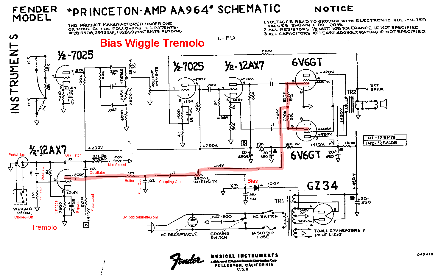
The tremolo voltage signal is fed into the fixed bias circuit to waiver the bias and therefore output volume.
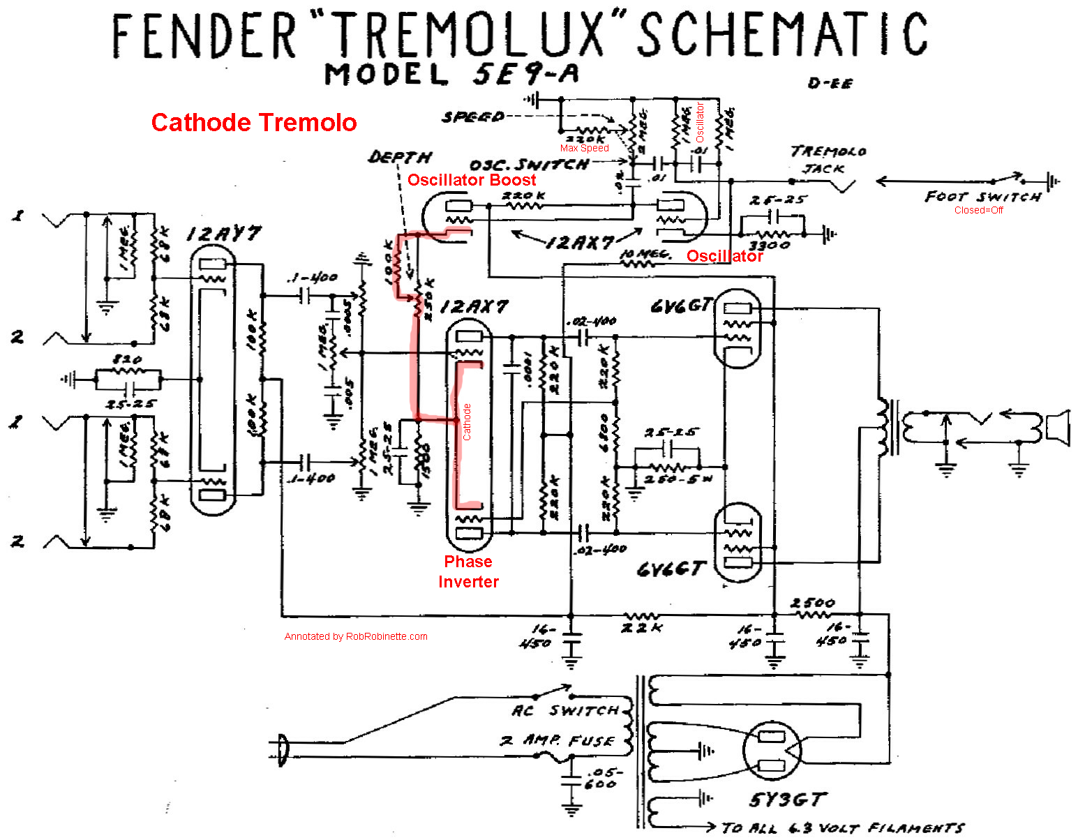
Tube Tremolo At the Preamp Cathode
The Fender 5E9A Tremolux applies the tremolo signal to the phase inverter cathode so it can be used in pretty much any amp: fixed bias, cathode bias and small or large power tube amps. It uses two triodes (whole tube) and consists of a standard oscillator plus an oscillator amplifier or booster. Again, the oscillator itself is very similar to the ones used above.
See the Compact Tremolo Add-On Circuit page for more info on tremolo circuits.
By Rob Robinette
References
RCA Corporation, RCA Receiving Tube Manual, RC30.
Merlin Blencowe, Designing Tube Preamps for Guitar and Bass, 2nd Edition. This is my personal favorite tube amp book.
Merlin Blencowe, Designing High-Fidelity Tube Preamps
Morgan Jones, Valve Amplifiers, 4th Edition.
Richard Kuehnel, Circuit Analysis of a Legendary Tube Amplifier: The Fender Bassman 5F6-A, 3rd Edition.
Richard Kuehnel, Vacuum Tube Circuit Design: Guitar Amplifier Preamps, 2nd Edition.
Richard Kuehnel, Vacuum Tube Circuit Design: Guitar Amplifier Power Amps
Robert C. Megantz, Design and Construction of Tube Guitar Amplifiers
Neumann & Irving, Guitar Amplifier Overdrive, A Visual Tour It's fairly technical but it's the only book written specifically about guitar amplifier overdrive. It includes many graphs to help make the material easier to understand.
T.E. Rutt, Vacuum Tube Triode Nonlinearity as Part of The Electric Guitar Sound
[ How the 5E3 Deluxe Works ] [ Deluxe Models ] [ My 5E3 Build ] [ The Trainwreck Pages ] [ Fender Input Jacks ] [ B9A Prototype Boards ]