[ How Amps Work ] [ Overdrive ] [ 5E3 Mods ] [ 5F6A Mods ] [ AB763 Mods ] Board ]
ValveWizard B9A development board
By Rob Robinette
The following are tube guitar amplifier layouts using the ValveWizard's B9A development board PCBs. The boards make for easy tube circuit prototyping and allow a modular mix-and-match approach to prototyping. It is easy to stitch together an amp using one B9A board with the Fender 5E3 Deluxe preamp with the 5F6A Bassman phase inverter and the Vox AC15 power amp.
For info on the boards and ordering (about $7 each) see the B9A development board website. You can use the freeware program DIY Layout Creator to create layouts by downloading the B9A development board DIYLC file and B9A pdf.
WARNING: A tube amplifier chassis contains lethal high voltage even when unplugged--sometimes over 700 volts AC and 500 volts DC. If you have not been trained to work with high voltage then have an amp technician service your amp. Never touch the amplifier chassis with one hand while probing with the other hand because a lethal shock can run between your arms through your heart. Use just one hand when working on a powered amp. See more tube amplifier safety info here.
The Fender 5E3 Deluxe Preamp Using a ValveWizard B9A development board
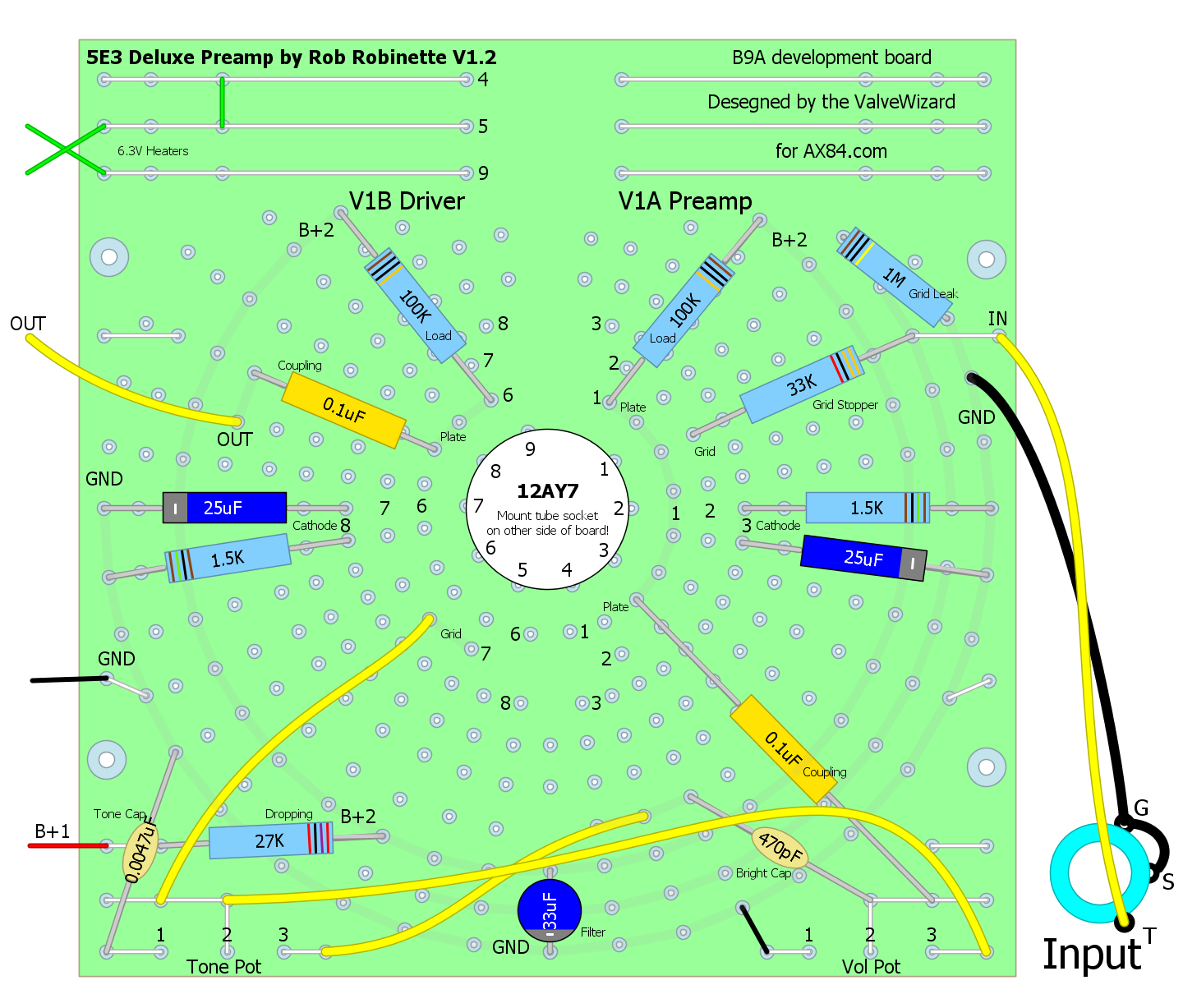
This is the 1957 Fender Deluxe 5E3 Bright Channel preamp. Note that you have to mount the tube socket on the other side of the board. Download the 5E3 Preamp DIYLC here.
The Deluxe Micro Power Amp Using a B9A board
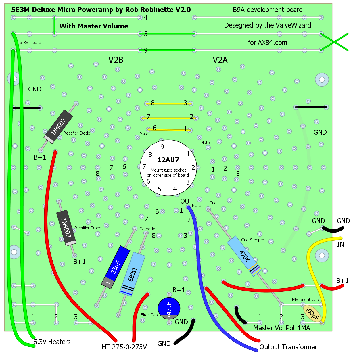
This power amp uses both triodes of a 12AT7 in parallel. Shown with Master Volume at bottom right. Note that you have to mount the tube socket on the other side of the board. Download the DIYLC file here.
The Complete 5E3M Deluxe Micro Using Diode Rectification & Two B9A Boards
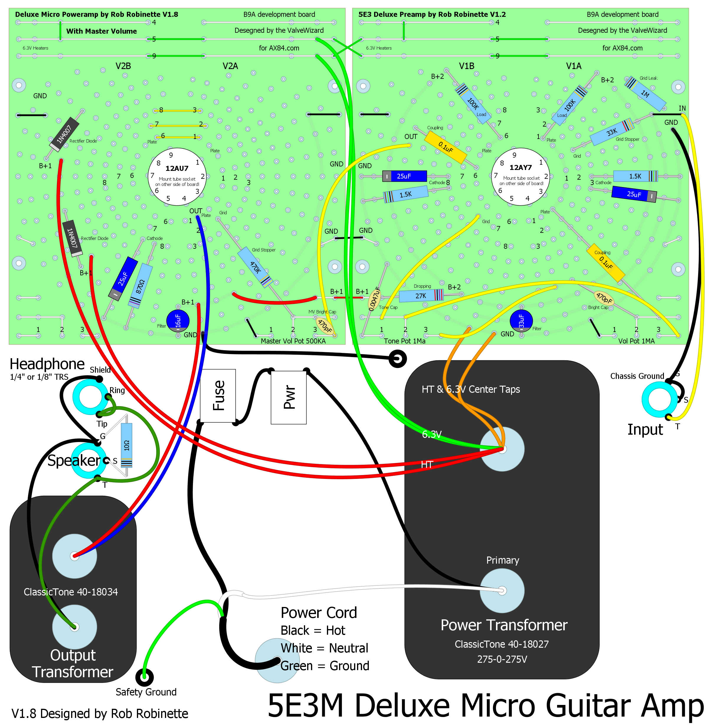
Click image to view the hi-res PDF layout. Download the DIYLC file here.
Deluxe Micro Preamp (left) and Power Amp (right)
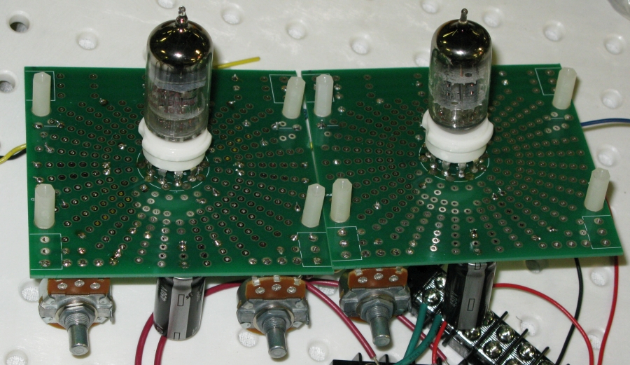
Tube side above, component side below.
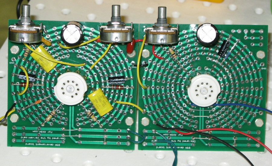
This side of the board should not have tube sockets but this was my first use of the B9A board and I didn't read the fine print on the backside of the board and ended up with sockets on both sides of the boards. Note that you must mount the tube socket on the side of the board marked "Fit tube this side."
For more information on the Deluxe Micro amplifier see the Deluxe Micro webpage.
The Complete Deluxe Micro With Tube Rectification Using Three B9A Boards
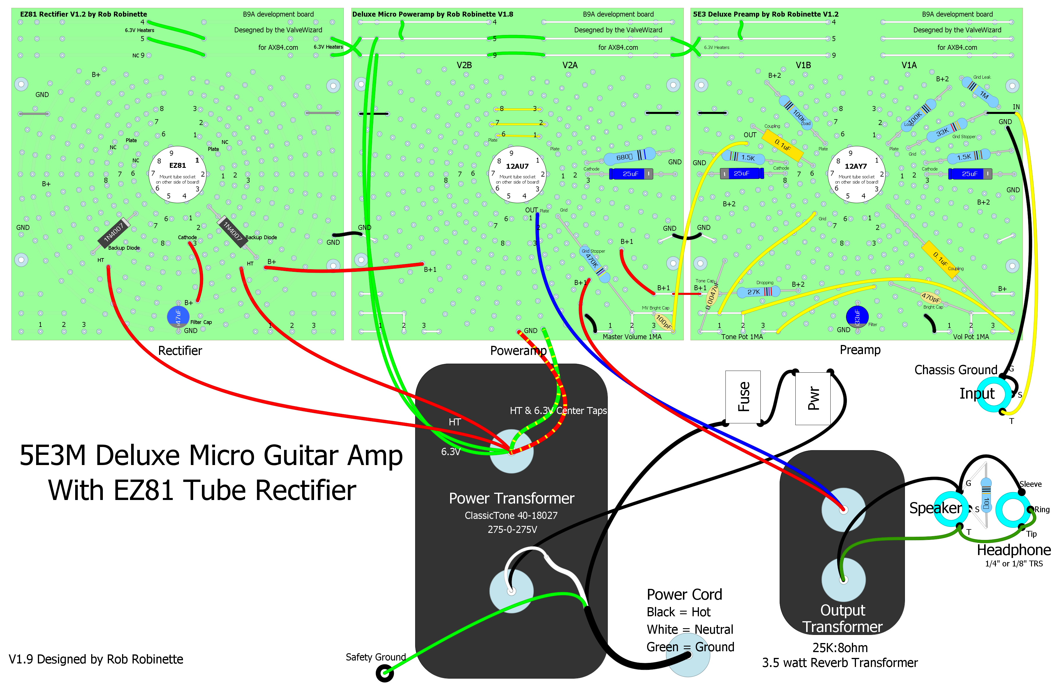
EZ81 tube rectifier at far left. Click on the image to see the hi-res pdf. Download the DIYLC file here.
Self-Split Push-Pull Power Amp
Self-Split Power Amp B9A Board
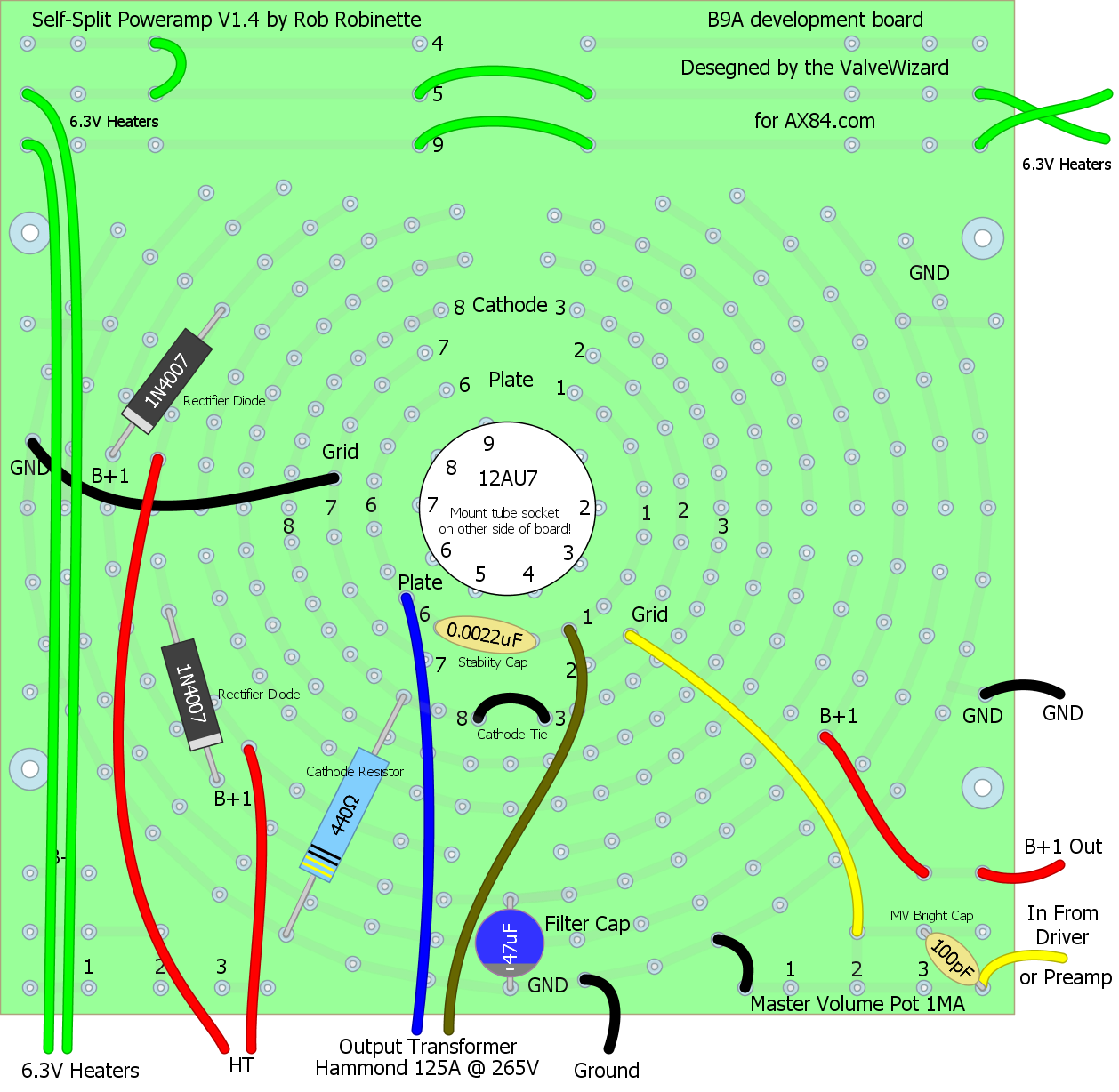
Puts out almost twice as much power as the single ended parallel 12AU7. Note the 500KA Master Volume pot at bottom right replaces the 330K Grid Leak resistor in the schematic above. Optional 2 diode rectifier (left side of board) supplies B+ voltage for the rest of the amplifier. Download the DIYLC file here.
Component Side of Self-Split Power Amp B9A Board
Super simple power amp design. The 500KA Master Volume pot and brite cap will go in the three holes at bottom right.
Socket Side of Self-Split Power Amp B9A Board
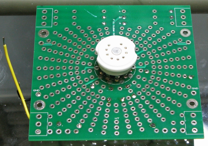
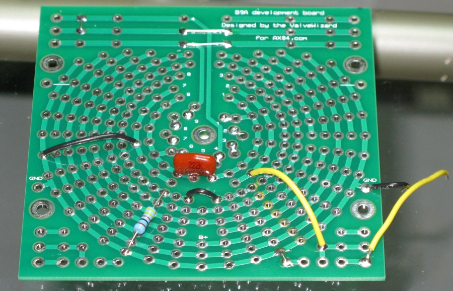
5F6A Tweed Bassman Bright Hi Preamp
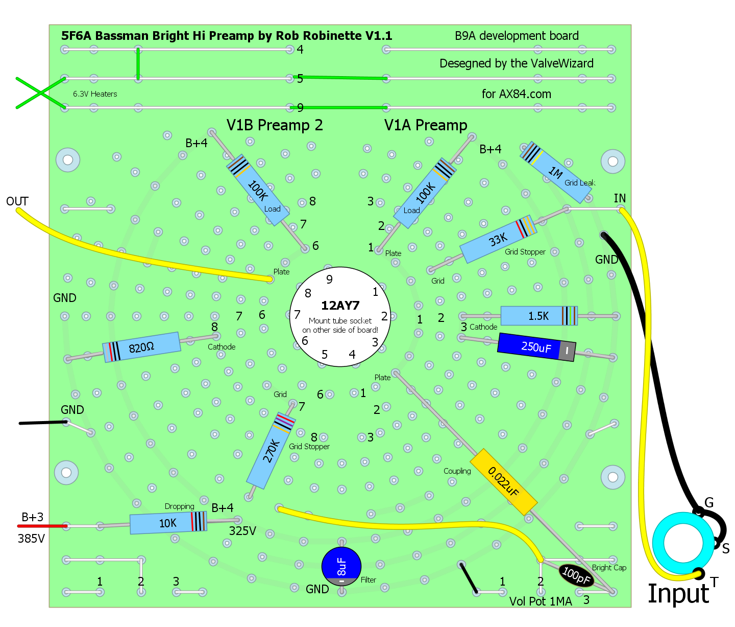
Download the Preamp DIYLC file here.
5F6A Tweed Bassman Long Tail Pair Phase Inverter
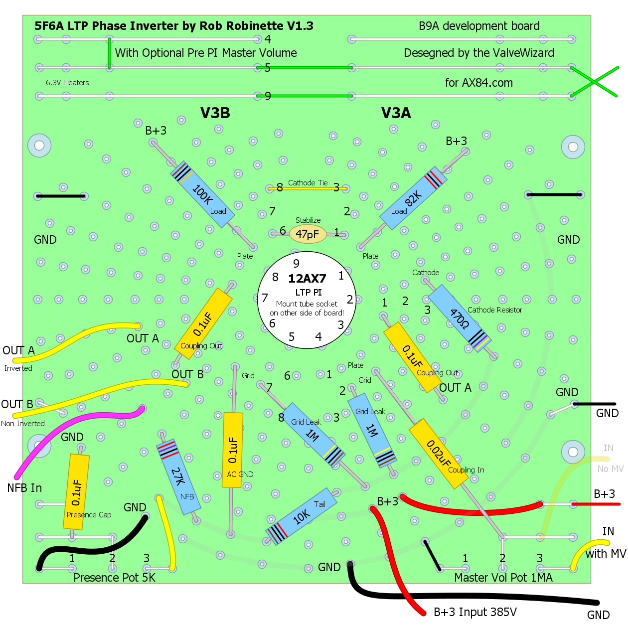
Download the LTP DIYLC file here.
5E3 Preamp to 5F6A Long Tail Pair Phase Inverter
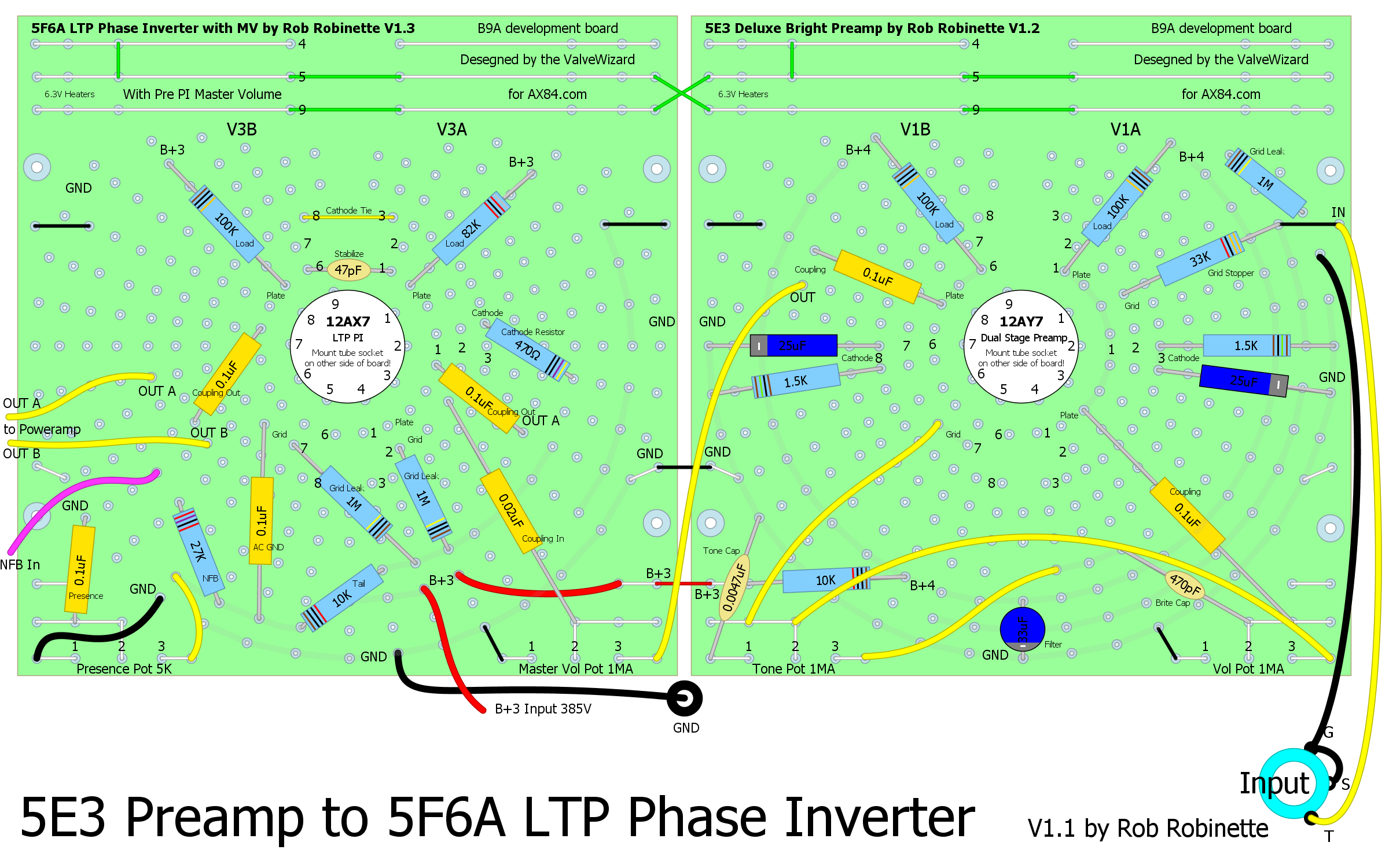
Download the DIYLC file here.
AC15 EL84 Push-Pull Power Amp
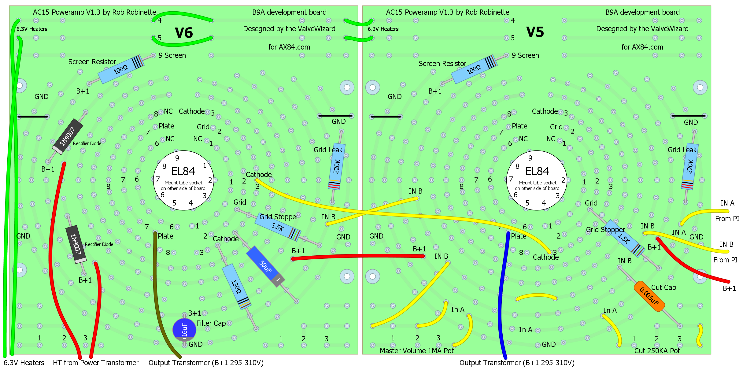
Download the AC15 Power Amp DIYLC file here.
EZ81 Tube Rectifier
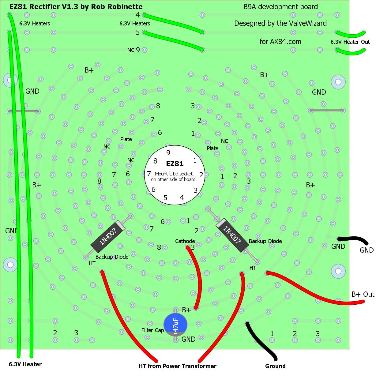
The EZ81 uses a standard 9-pin socket and 6.3 volts and 1 amp for cathode heat. It can put out a max of 150 milliamps (0.15A) with a 350-0-350V power transformer. Backup diodes pre-rectify the high voltage AC from the power transformer to prevent damage to the amp if the rectifier tube fails.
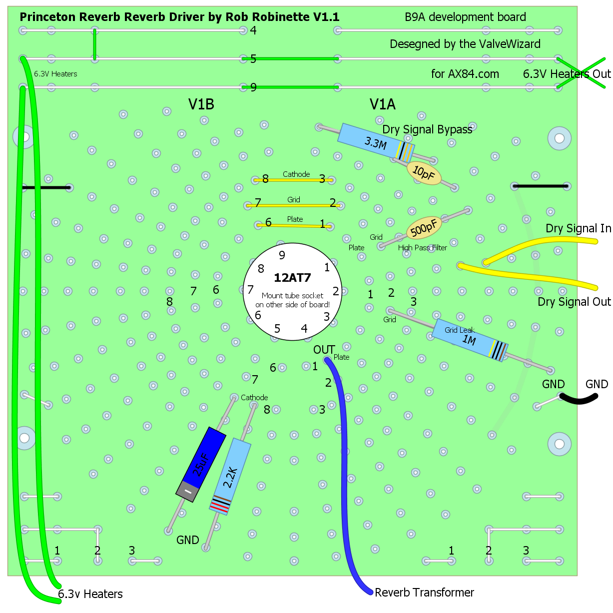
AA1164 Blackface Princeton Reverb Reverb Driver
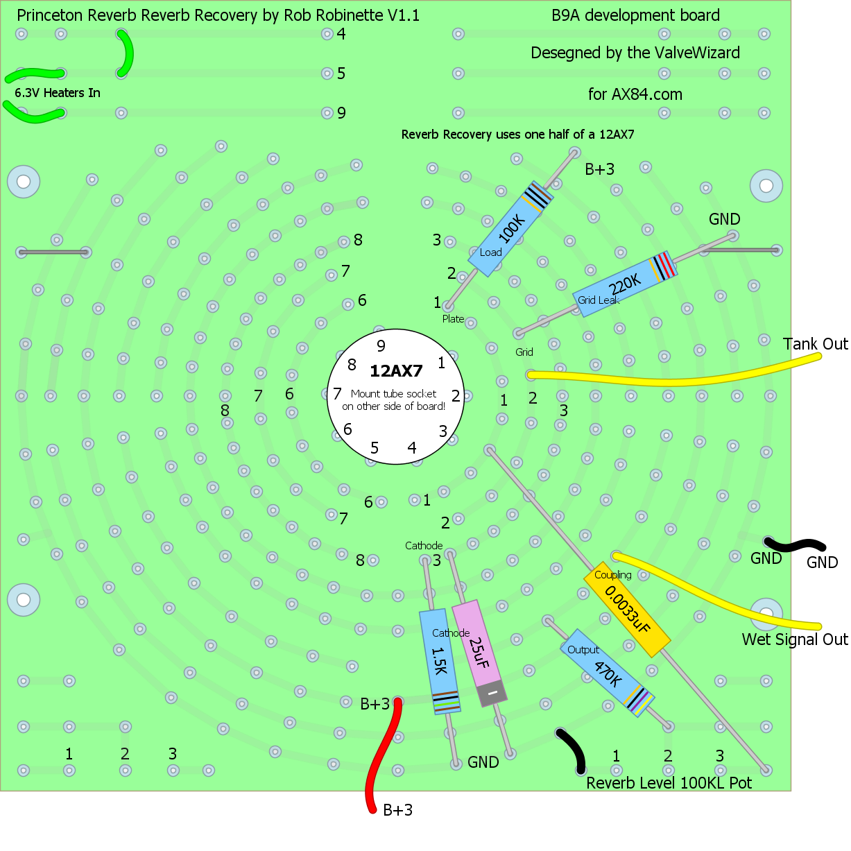
AA1164 Blackface Princeton Reverb Reverb Recovery
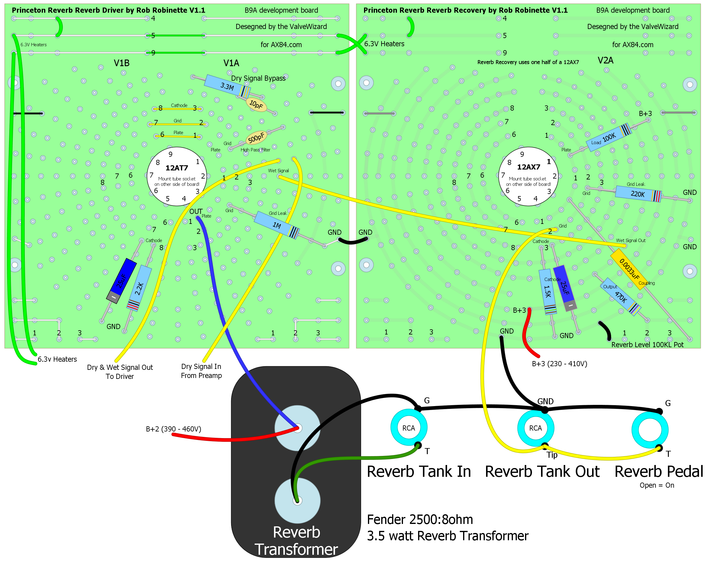
AA1164 Blackface Princeton Reverb Reverb Add On Circuit
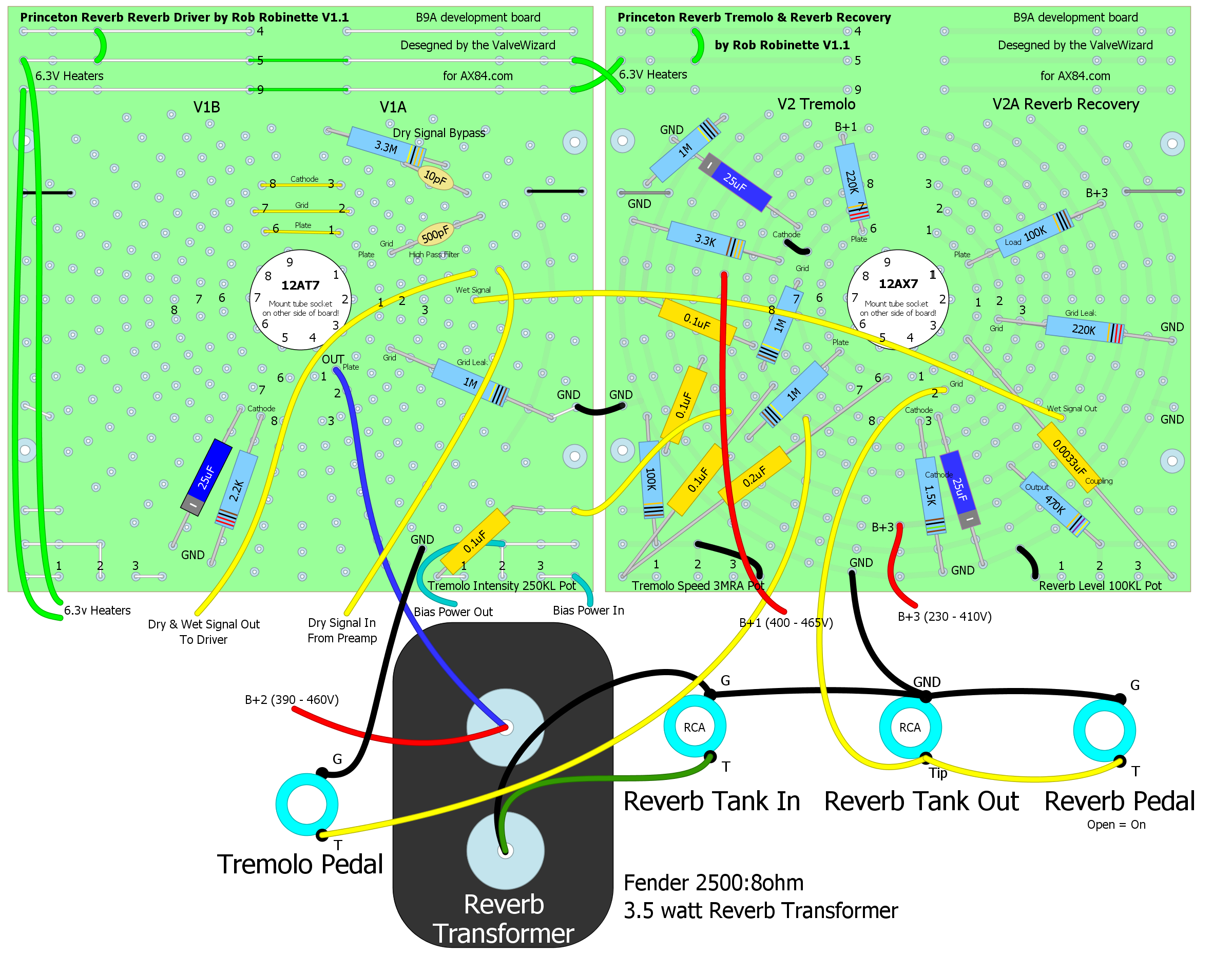
AA1164 Blackface Princeton Reverb Tremolo & Reverb Add On Circuit
Blank B9A Layout
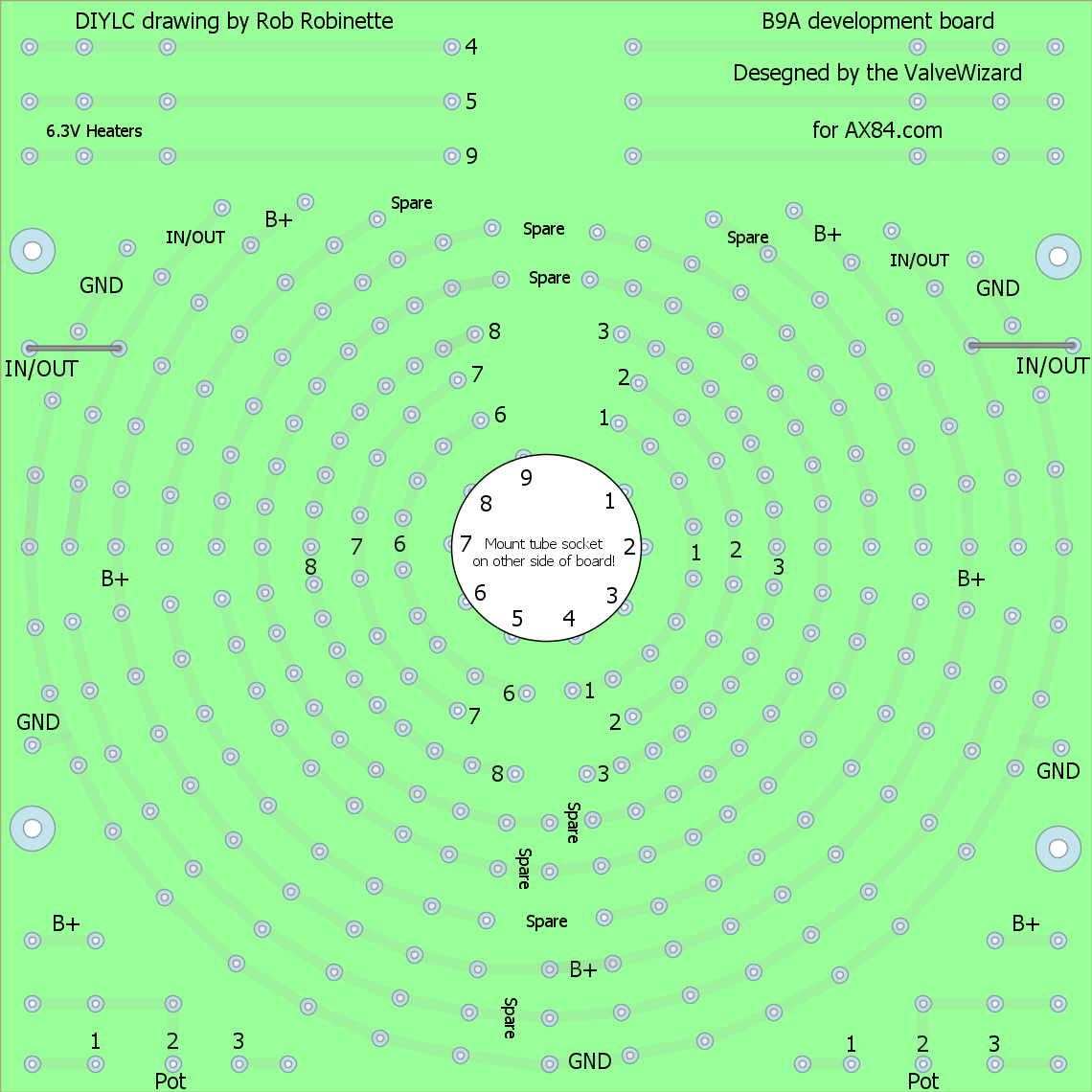
The inner 3 rings are dedicated to the plate, grid and cathode of the 12A*7 tubes. The 12A*7 heater pins 4,5 and 9 have their connections at the top of the board but remember to jumper pins 4 and 5 together. Note how the Ground and B+ rings run all the way around the circle but some of the 'Spare' rings are divided into 1, 3 or 4 parts around the ring. For info on the boards and ordering see the B9A development board website. You can use the freeware program DIY Layout Creator to create layouts by downloading the B9A development board DIYLC file and B9A pdf.
By Rob Robinette
[ How Amps Work ] [ Overdrive ] [ 5E3 Mods ] [ 5F6A Mods ] [ AB763 Mods ] [ DRRI & 68 CDR Mods ] [ How the 5E3 Deluxe Works ] [ How the AB763 Works ] [ AB763 Models ] [ Tube Bias Calculator ] [ Amp Troubleshooting ] [ Deluxe Models ] [ Deluxe Micro Amp ] [ Bassman Micro Amp ] [ Champ Micro Amp ] [ My 5E3 Build ] [ Reverb & Tremolo ] [ SixShooter ] [ Spice Analysis ] [ VHT Special 6 Ultra Mods ] [ Telecaster Mods ] [ Android Tube Bias Calculator App ] [ The Trainwreck Pages ] [ Fender Input Jacks ] [ B9A Prototype Board ]