[ How Amps Work ] [ Overdrive ] [ 5E3 Mods ] [ 5F6A Mods ] [ AB763 Mods ]
By Rob Robinette
The sooner you learn to read amplifier schematics the sooner you'll be able to analyze classic amp circuits and learn how the masters of amp design voiced their amps. It's much easier to analyze an amp circuit by studying its schematic than looking at its layout diagram. The key to learning to read amp schematics is to start small with the Fender 5F1 Champ amplifier schematic and focus on one component at a time to keep from being overwhelmed. Once you can read the simple Champ schematic you'll be able to figure out more complicated amp schematics.
WARNING: A tube amplifier chassis contains lethal high voltage even when unplugged--sometimes over 700 volts AC and 500 volts DC. If you have not been trained to work with high voltage then have an amp technician service your amp. Never touch the amplifier chassis with one hand while probing with the other hand because a lethal shock can run between your arms through your heart. Use just one hand when working on a powered amp. See more tube amplifier safety info here.
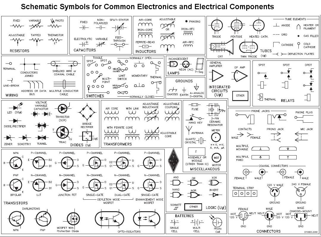
We'll start with learning pretty much all the schematic symbols you'll need for tube amps in this little schematic legend:
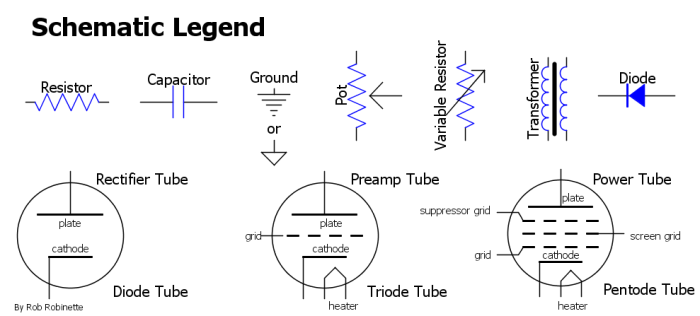
Common amp component symbols. You can right-click this graphic and select "Open image in new tab" or "Save image as" to make it easier to access while looking at the schematics below.
Lets start by looking at the simple standard tube amplification circuit that you will see again and again as you study tube amp schematics.
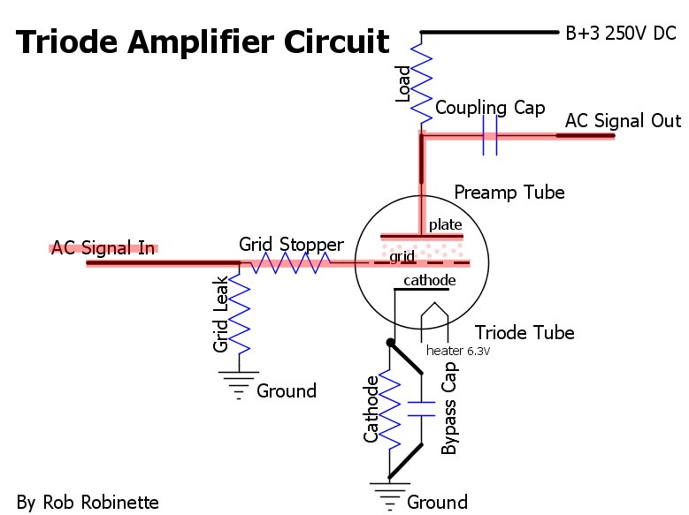
Guitar signal shown in pink enters the tube on the left at "AC Signal In." The guitar signal flows through the Grid Stopper resistor to the tube's Grid, then out the tube's Plate, through the Coupling capacitor and on to the next amp circuit. The Grid Leak resistor bleeds off unwanted captured electrons (grid current) to keep the grid at zero volts DC. The optional Grid Stopper resistor filters high frequencies above human hearing. The Cathode resistor generates the bias voltage between the cathode and grid. The optional Bypass capacitor boosts gain by acting as an electron reservoir. The tube's Cathode is the source of electrons. The Grid is the "valve" that controls the flow of electrons through the tube. The Plate is charged with high voltage DC to pull electrons from the cathode, through the grid to the Plate. The Load resistor transforms the circuit from a current amplifier to a voltage amplifier. The Coupling cap keeps the Plate's high voltage DC from flowing downstream but allows the guitar AC signal voltage to pass. This tube is a 'triode' which means it has three electrodes: the grid, plate and cathode.
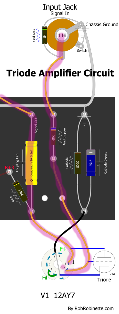
The same triode amplifier circuit's layout diagram.
Only 26 electronic components are needed to make a great sounding amplifier.
Every component's function is listed. The signal flow in red starts at Input Jack 1 at the far left. V1A is one half of tube V1, V1B is the other half. The component numbers match the layout below so you can compare the layout and schematic. Click the image for the full size schematic.
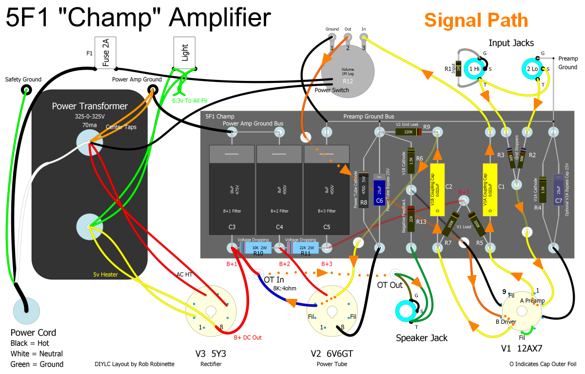
Notice how convoluted the signal path is (shown with orange arrows) on this layout diagram. It's much more difficult to figure out what's going on in the amp using a layout diagram like this compared to using a schematic. The component numbers match the schematic so you can compare the layout and schematic.
I always start my schematic analysis by tracing the guitar signal through the amp. That way I can focus on the most important components that "voice" the amp such as the cathode resistors and caps, plate load resistors and coupling caps. The signal path is shown by the red line in the above schematic so follow along as I trace the guitar signal through the schematic.
After entering the Input jack at the far left of the schematic the first thing the guitar signal encounters is the R1 Input resistor. The "1MEG." label means the value of the resistor is 1 megaohm (1 million ohms). You will also see "1M" for 1 megaohm. The Input resistor set's the amp's input impedance. I'm not going to detail the function of these components here because I do that in the "How Tube Amps Work" webpage so see that page for more detail on component functions.
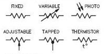
"Adjustable" is our typical pot or potentiometer.
Notice that in the schematic wires that cross and connect have a "connection dot" while wires that cross and do not connect do not have a dot. Some schematics will show non-connecting cross wires make a "hop" over the wire to make it clear they do not connect.
Next the guitar signal flows through both the R2 and R3 Grid Stopper resistors. Their value is 68K (68 kilohms or 68,000 ohms). Grid Stopper resistors remove audio frequencies above human hearing to help keep the amplifier from oscillating (freaking out).
After the Grid Stopper resistors the signal flows on to the tube V1A Grid. The preamp tube V1 (Valve 1) is made up of two separate triodes called A and B. The A triode (V1A) is the first gain stage and the B triode (V1B) is the second gain stage. The guitar signal on the V1A Grid controls the flow of electrons from the tube's Cathode to the Plate. The R4 1500 ohm (1.5k) Cathode resistor generates the triode's bias voltage. You will also see 1.5K ohms shown on schematics as 1K5, the K or M is placed where the decimal goes. An optional Cathode Bypass capacitor can be placed in parallel with the Cathode resistor to boost gain.
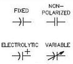
Note how the straight plate is the + plate and the curved plate symbolizes the negative terminal in polarized caps. Variable caps are very rare in tube amps but common in radios.
Most cathode bypass capacitors are electrolytic which are polarized with a + and - terminal. If you don't see a + and - on the schematic it means the cap is connected - (negative) to ground. About the only time you'll see a polarized cap connected + to ground is in a power tube bias circuit which creates a negative voltage (see the 5F6A Bassman schematic below for an example).
The R5 100k (100,000 ohms) Plate Load resistor transforms the triode circuit from a current amplifier to a voltage amplifier. The signal leaves the tube through the Plate and flows to the C1 Coupling capacitor which is rated at .02uF (micro Farad) and 600 volts. It stops high voltage DC but allows the AC guitar signal to pass on to the 1 megaohm Volume pot which is simply a variable voltage divider or potentiometer. The arrow part of the pot symbol symbolizes the pot's wiper.
The guitar signal flows out the pot's wiper directly to V1B's Grid for a second round of amplification. The R13 Negative Feedback (NFB) resistor shown at top center sends a little of the Output Transformer secondary signal to the V1B cathode to lower amp noise and distortion. Resistor R13 controls how much NFB signal passes to the cathode.
The guitar signal exits the tube at the Plate. Like V1A, a 100k Plate Load resistor and .02uF coupling cap are encountered. Resistor R9 is the V2 Power Tube Grid Leak resistor which bleeds off grid current to keep the grid near zero volts DC. The Power Tube is the final amplification stage. It has a 470 ohm Cathode resistor which is bypassed (paralleled) by a 25uF 25 volt Cathode Bypass capacitor which boosts the power tube's gain.
The guitar signal flows out of the Power Tube and into the Output Transformer primary winding where it induces a lower voltage but higher current guitar signal in the Output Transformer secondary winding. This low impedance signal drives the Speaker's voice coil and cone.
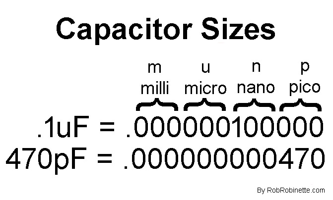
Use this chart to help convert capacitor size such as: .1uF = 100nF and .47nF = 470pF
That's it for the signal path, now let's examine the amp's power supply shown at the bottom of the schematic. AC wall power from the Power Cord flows through the ON/OFF "AC Switch" and on to the Power Transformer (shown at bottom center) which steps up the wall voltage to 325 volts RMS (root mean square average) AC for the high voltage supply and steps it down to 6.3 volts for the preamp and power tube heater filaments and 5 volts for the rectifier tube heater. The V3 Rectifier Tube transforms the 325v AC high voltage from the Power Transformer into 360 volts of high voltage DC which the amp needs to power the tubes.
High voltage DC flows out of the Rectifier Tube's cathode to a series of electrolytic Filter Capacitors (C3, C4 and C5) and Voltage Dropping resistors (R10 & R11). The big filter caps are electrolytic which are bipolar and have + and - terminals. They will normally be connected - (negative) to ground. If one is connected + (positive) to ground then the schematic will note that.
The filter caps and resistors work together to form RC (resistance-capacitance) low pass filters that remove the voltage ripple caused by the pulsing DC coming from the Rectifier Tube. The first power node at capacitor C3 powers the Output Transformer primary winding with 360 volts of DC. The second power node at C4 powers only the Power Tube Screen grid with 325 volts DC. The final power node at C5 powers the V1 Preamp Tube with 250 volts of DC.
For a more detailed explanation of how the 5F1 Champ amplifier works see How Tube Amps Work.
![]()
The down arrow pointing to "CW" means the direction the wiper moves when you turn the knob clockwise.
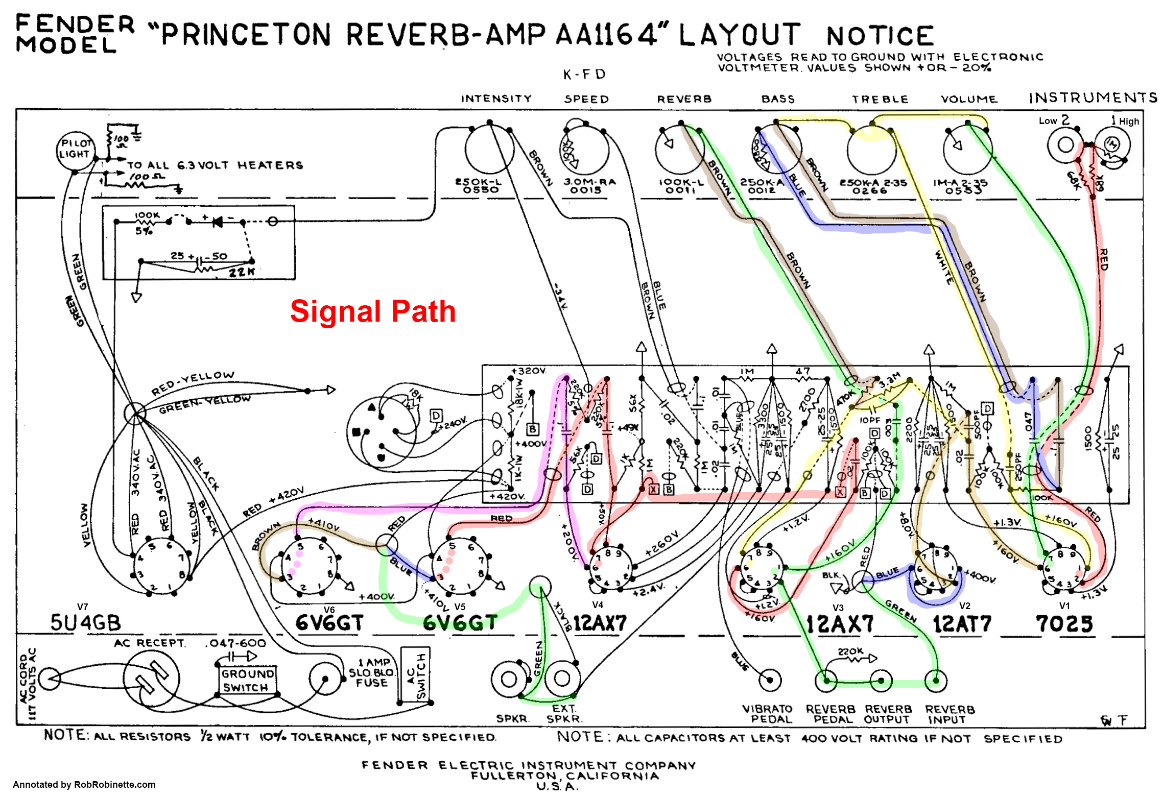
Signal path colors match on the schematic and layout.
You can use the following annotated guitar amplifier schematics to help you read other unlabeled amp schematics.
Once you get comfortable with the Champ schematic take a look at the 5E3 Deluxe schematic. It's a slightly more complex push-pull amp but it's surprisingly similar to the little Champ.
Signal flow shown as the thick gray line. Click the image to view the full size (readable) annotated schematic. A pdf version is here.
The 5E3's Phase Inverter V2B puts out two audio streams, one normal and one inverted. The two mirrored audio streams feed the two Power Tubes for push-pull operation.
The 1950's Fender 5F6-A Bassman is the grandfather to the world's high gain amplifiers. The Marshall JTM45 was an almost verbatim copy of the Bassman.

Note the Bias Filter Caps at center right have their + terminal connected to ground. All the other electrolytic caps are connected - (negative) to ground. What do all those parts do? Click on the graphic to see the full size and readable schematic.
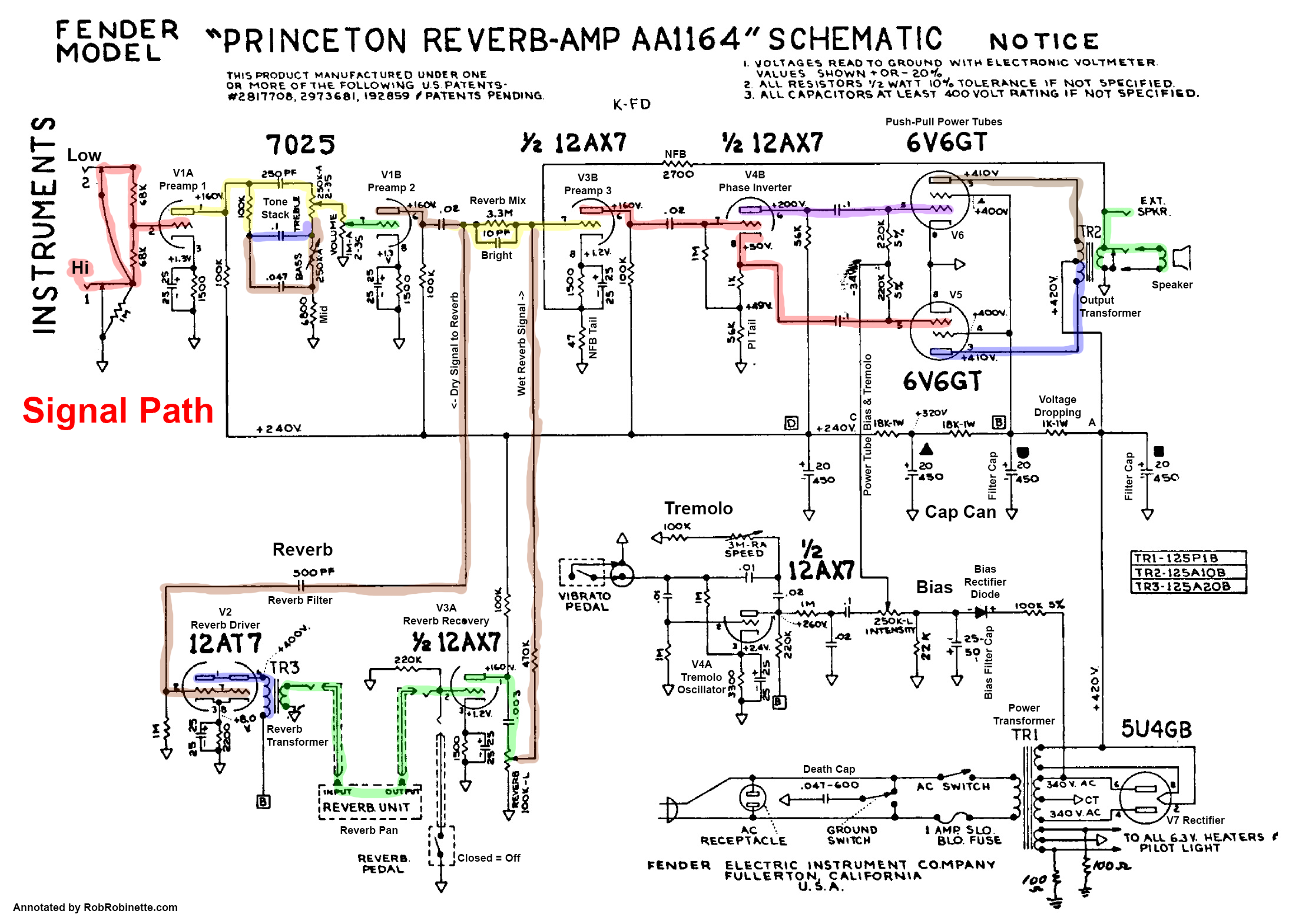
Here's another classic amp schematic that should look familiar after studying the Champ and Deluxe above, the 1963 Fender AB763 "Blackface" line of amps. Note the spring reverb (bottom left) and tremolo (bottom center).
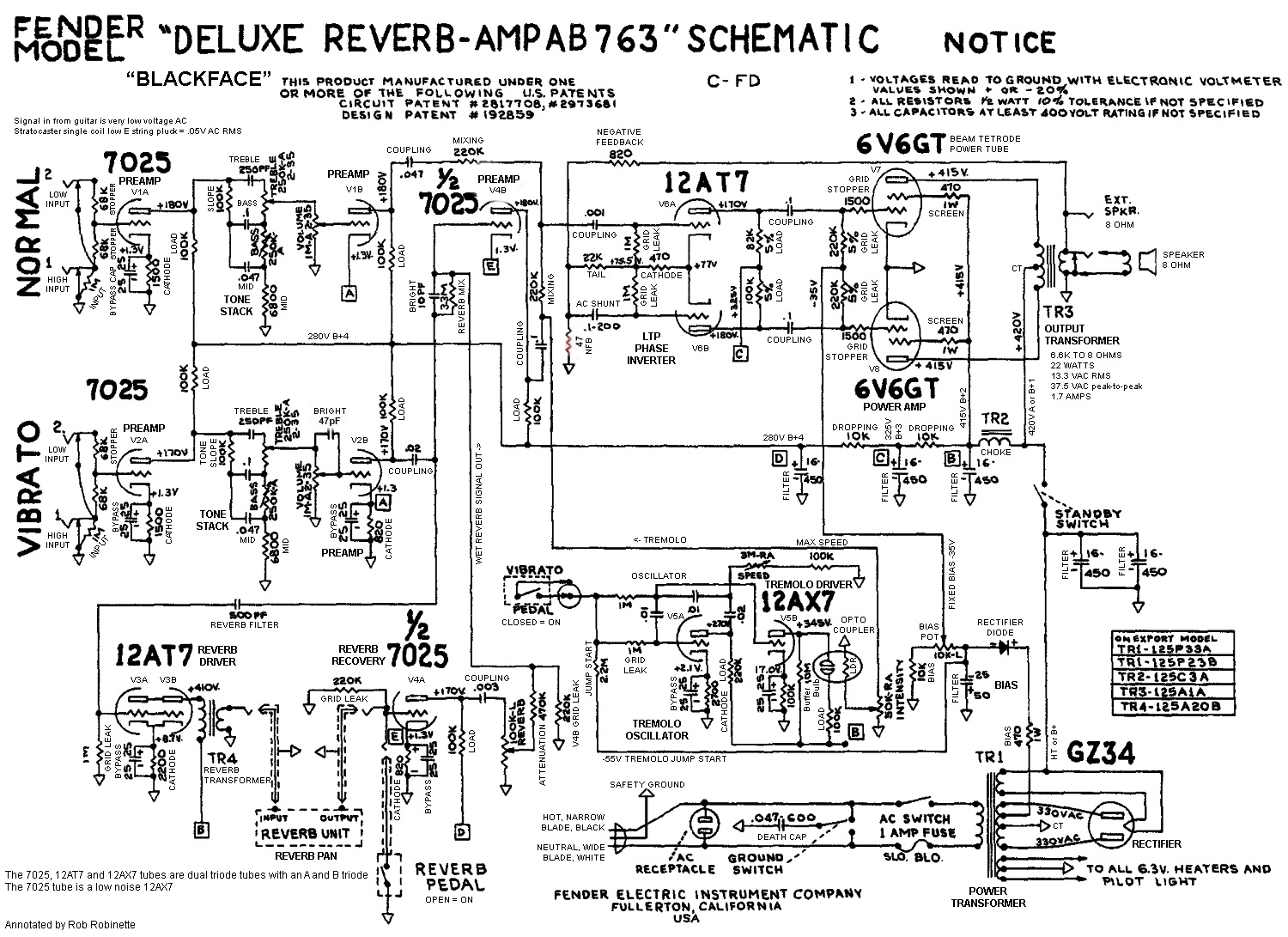
Notice the reverb circuit at lower left and the tremolo at lower center. Every component function is listed on this schematic. Click the image for the full size schematic.
The Plexi's topology is still very similar to the Fender 5F6-A Bassman shown above. The guitar signal enters at left at the I "Bright" Channel input jack. The signal is amplified by the V1B preamp stage then flows through the Volume I pot to the V2A preamp then directly through DC coupling (no coupling cap) to the V2B cathode follower which supplies the tone stack with a low impedance signal to keep the tone stack from loading down the guitar signal. After the Tone Stack the signal goes into the Phase Inverter. The Phase Inverter creates two mirror image signals that are 180 degrees out of phase to feed to the Power Tubes.
The guitar signal enters at far left at the High "Lead" Channel input jack. The signal is amplified by the V1B preamp stage then flows through the Preamp Volume pot to the V1A cold biased "cold clipper" gain stage which generates asymmetric clipping distortion. The signal then flows through the V2A preamp then directly through DC coupling (no coupling cap) to the V2B cathode follower which supplies the tone stack with a low impedance signal to keep the tone stack from loading down the guitar signal. After the Tone Stack the signal goes through the Master Volume and into the Phase Inverter. The Phase Inverter creates two mirror image signals that are 180 degrees out of phase to feed to the Power Tubes.
Note the arrows shown on all the pots in the Marshall preamp above. They indicate the direction of wiper movement when the pot is turned clockwise or "up."
Guitar signal from the Phase Inverter enters at far left and flows to the Power Tube grids. The signal is amplified and flows out the tube plates where one tube pushes the signal through the Output Transformer primary winding while the other power tube pulls. The high impedance signal (high voltage but low current) flowing through the Output Transformer primary winding induces a low impedance signal (low voltage but high current) in the secondary winding which is connected to the Speaker Jacks. The guitar signal then flows through the speaker's voice coil and generates a magnetic field. The magnetic field interacts with the speaker magnet and causes the voice coil and speaker cone to move in and out generating air pressure waves our ears perceive as the sweet sound of electric guitar.
For more info on how these Marshall amps work see this.
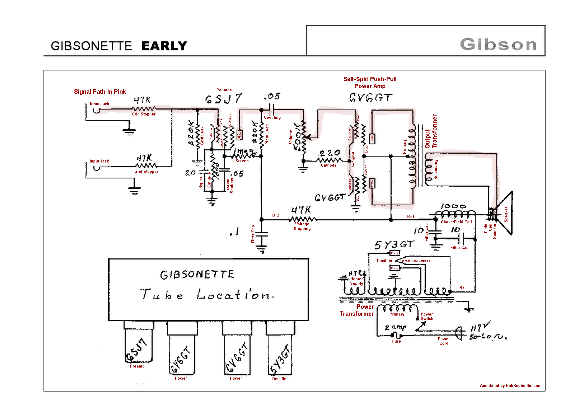
The early Gibsonette (mid-late 1940's) has an unusual design. It uses a single pentode stage for the preamp, a self-split push-pull power amp which requires no phase inverter and a field coil speaker. The self-split power amp works like this: The guitar signal on the upper power tube grid changes the current flowing through the tube which causes a voltage drop across the cathode resistor. This voltage drop is also present on the lower power tube cathode and since the lower grid is grounded (common grid) the voltage changes on the cathode affect the current flowing through the lower power tube. The speaker field coil is an electromagnet that takes the place of the speaker permanent magnet. The field coil also acts as the choke.
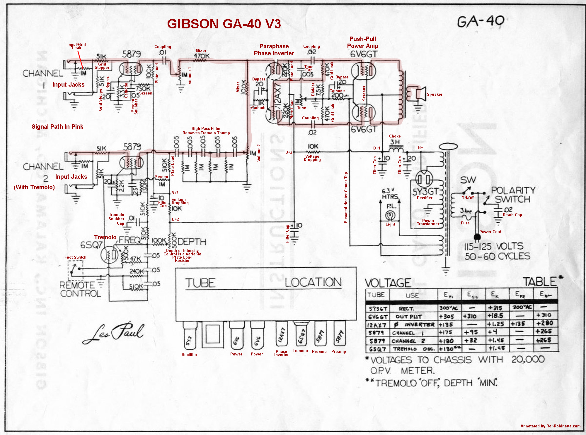
The GA-40 V3 uses one 5879 pentode per channel as a single preamp stage. The paraphase phase inverter lower triode gets its signal to its grid through the upper 470k grid leak resistor. The tremolo oscillation is fed to the channel 2 preamp plate. The "Tremolo High Pass Filter" is a fifth order high pass filter which removes tremolo thumping that can be created in the tremolo oscillation. Each RC network stage rolls off at a slope of 6dB per octave at 32Hz which creates a very steep filter roll off. This allows the corner frequency to be set low enough to allow normal bass response in the tremolo channel (Channel 2) while still killing tremolo thump.
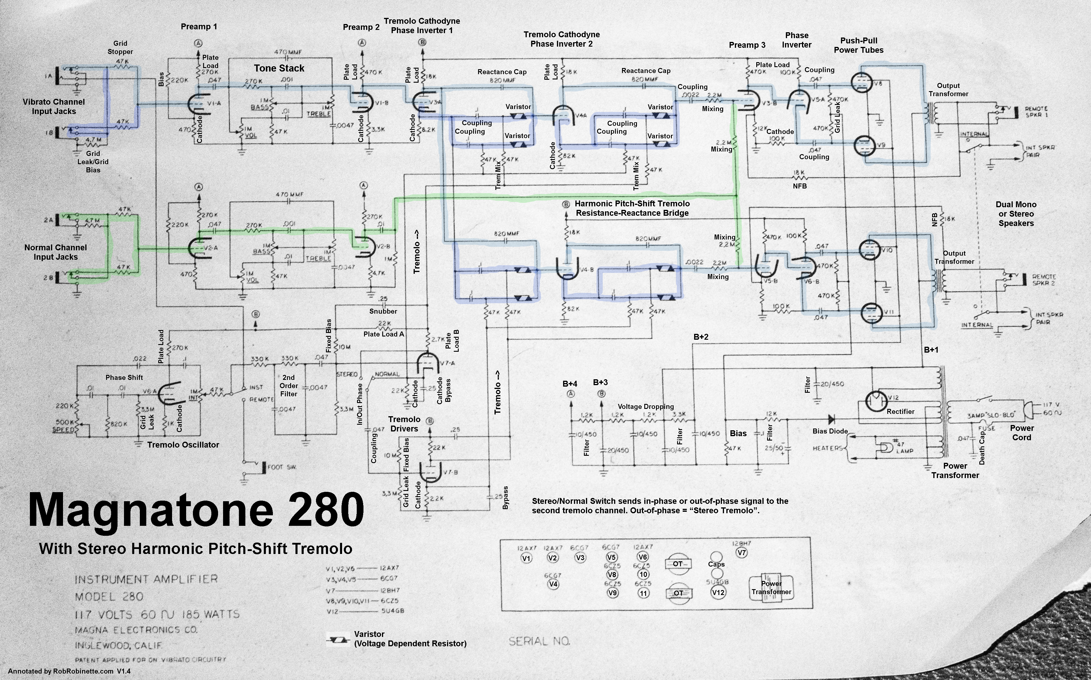
This amplifier won the Tremolo War with by far the most complex and intricate tremolo design. Each stereo channel has its own tremolo driver, harmonic pitch-shift circuit, power amp and speaker. Vibrato Channel signal path shown in blue. Normal Channel signal path shown in green. Tremolo Oscillator and Tremolo Drivers at lower left. Dual channel Harmonic Pitch-Shift circuits at upper center. Click image to see full size schematic.
Don't worry, you don't have to memorize this schematic legend from the ARRL.
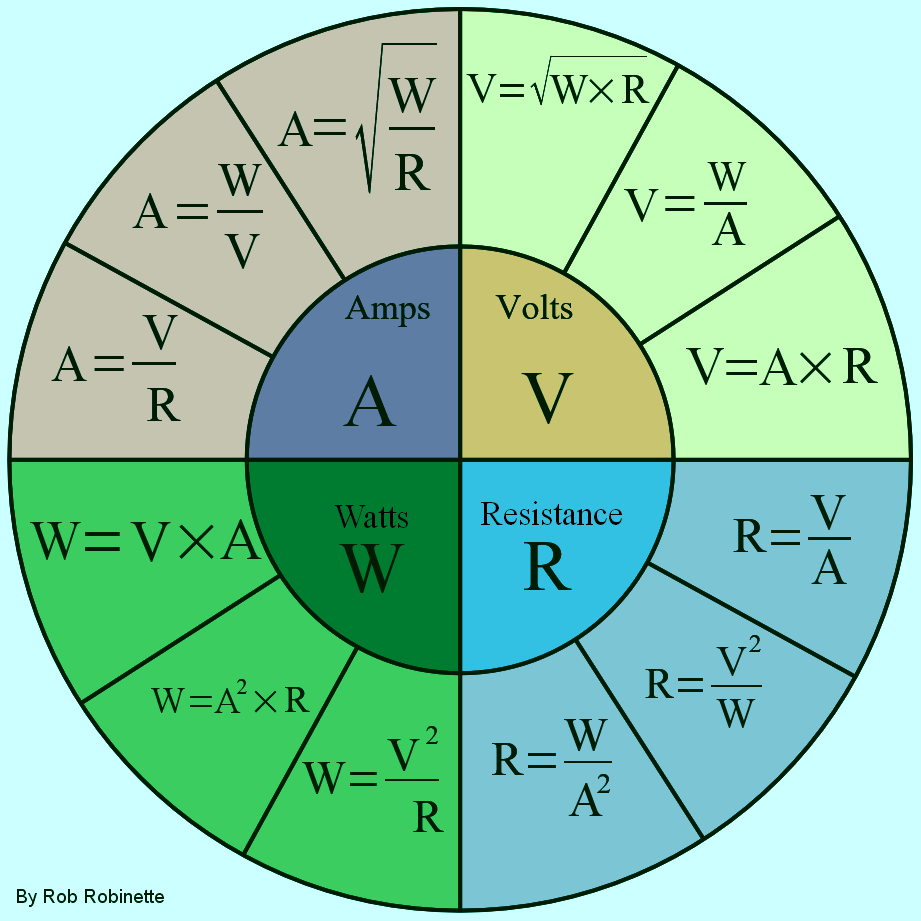
It's much easier for me to remember this stuff if I use A, V, R and W for Amps, Volts, Resistance and Watts in these equations. For example the lower left Watts section shows three ways to calculate power: Volts * Amps or Amps squared * Resistance or Volts squared / Resistance.
More info on Ohm's Law.
The first time I saw the equation for calculating the resistance of resistors in parallel I had a mental meltdown. It actually stopped me in my tracks as I attempted to self-learn electronics back in high school. Then I discovered the calculator's 1/x or inverse key that made this equation super simple.
Let's say you have three resistors in parallel: R1 is 100 ohms, R2 is 200 ohms and R3 is 300 ohms. All three resistors have equal voltage across them (electronic pressure) of 12 volts. Since the 100 ohm resistor is the path of least resistance it will flow more current than the 200 and 300 ohm resistors.
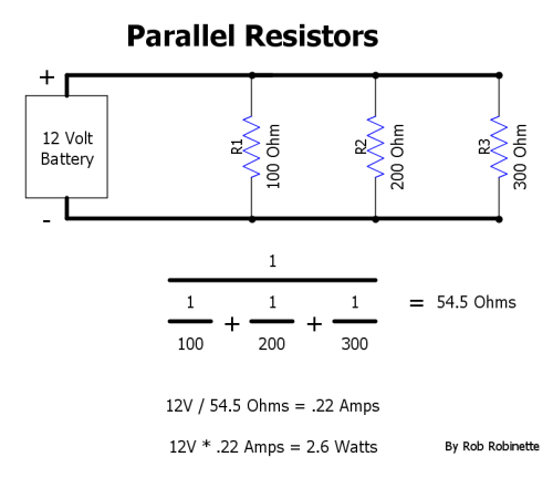
Circuit total resistance = 54.5 ohms. Using Ohm's Law current = .22 amps, power = 2.6 watts.
This would be the key sequence on the calculator (even the Windows built in calculator has a 1/x key):
100 1/x + 200 1/x + 300 1/x = 1/x
Don't forget that last 1/x key, it's for the 1/ on the top of the equation. 54.5 ohms should be showing on the calculator screen when you hit that last 1/x key. Give it a try right now, open your computer's on screen calculator and follow the key sequence. For the built-in Windows calculator you have to click on "Settings", select "Scientific" and you may have to click on the up arrow to see 1/x.
When I first got into electronics I had a hard time understanding voltage dividers but they are really pretty simple. Understanding them is important because a tube amp is full of them. Even tone controls and tone stacks can be thought of as voltage dividers. Click on this link for more info.
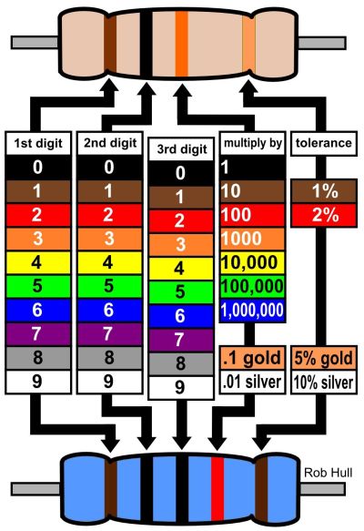
Note the 3-band resistor on top and 4-band on the bottom.
By Rob Robinette
RCA Corporation, RCA Receiving Tube Manual, RC30.
Merlin Blencowe, Designing Tube Preamps for Guitar and Bass, 2nd Edition.
Merlin Blencowe, Designing High-Fidelity Tube Preamps
Morgan Jones, Valve Amplifiers, 4th Edition.
Richard Kuehnel, Circuit Analysis of a Legendary Tube Amplifier: The Fender Bassman 5F6-A, 3rd Edition.
Richard Kuehnel, Vacuum Tube Circuit Design: Guitar Amplifier Preamps, 2nd Edition.
Richard Kuehnel, Vacuum Tube Circuit Design: Guitar Amplifier Power Amps
Robert C. Megantz, Design and Construction of Tube Guitar Amplifiers
Neumann & Irving, Guitar Amplifier Overdrive, A Visual Tour It's fairly technical but it's the only book written specifically about guitar amplifier overdrive. It includes many graphs to help make the material easier to understand.
T.E. Rutt, Vacuum Tube Triode Nonlinearity as Part of The Electric Guitar Sound
[ How the 5E3 Deluxe Works ] [ Deluxe Models ] [ DRRI & 68 CDR Mods ] [ Amp Troubleshooting ] [ My 5E3 Build ] [ Spice Analysis ] [ The Trainwreck Pages ] [ Fender Input Jacks ] [ B9A Prototype Boards ]