Photo by Rob Robinette
How to Voice a Tube Amplifier
By Rob Robinette
There are many ways to tweak the tone or "voice" of a guitar tube amplifier. Amp designers and modders can alter the clean and overdrive tone by changing component values, adding components, removing components, adding gain stages or even adding complete circuits like negative feedback. This page also discusses how your amp's controls work which will help you get the most out of your guitar and amp. Knowing what a resonance control or cut control actually do to the guitar signal can make you a better player.
You can tweak the voice early in the amp circuit for the greatest overall effect, especially on the overdrive tone, or you can tweak it late for minimal side effect. It's ideal to have early and late tone controls in an amplifier circuit to offer the most versatility. This is especially true in high gain amps with lots of preamp distortion. Why can't you just turn down the tone or treble control to remove overdrive fizz and ice pick highs? Because they are typically caused by harmonic and intermodulation distortion added by the overdriven stages in the amp--after the tone controls. Using an early-in-the-circuit tone control to remove fizz and ice pick can smother the tone because you not only remove high frequencies but also all the high frequency harmonics that would have been generated as the guitar signal cascaded through the gain stages. A late-in-the-circuit tone control can usually remove the fizz and ice pick without killing the lush and layered overdrive harmonics and sparkle.
Bass tends to work the opposite way. An early bass tone control can reduce overdrive mud and keep the low end tight. I have seen amps with the bass and mid controls early in the preamp but place the treble control after the last preamp gain stage which is probably the best way.
I'm a fan of adding a VOX style Cut control which trims high frequencies very late in the amp circuit--from the power tube input. It allows you to do a final tweak of the overdriven signal to darken it to taste without affecting the substance of the overdrive tone.
An added bonus of many of the tone tweaks on this page is they can help suppress oscillation and boost amplifier stability.
The higher the gain of an amplifier the more critical its voicing becomes. The Fender 5E3 Deluxe is beautifully voiced with rich overtones and a full bodied if not lose bottom end. Its clean tone is exceptional and when lightly overdriven sounds wonderful but push the amp too hard and all those low frequencies running through the amp wreck havoc on the amplifier circuitry. The 5E3's big coupling and cathode bypass caps and lack of grid stopper resistors all work together to cause extreme blocking distortion known as "farting out." The 5E3's simple amplifier circuit can be changed into a gain monster with the help of a boost pedal and a few component swaps. Reducing the size of the coupling and bypass caps and the addition of some grid stopper resistors can allow you to play Van Halen covers with the best of them. It just comes down to tweaking the voice.
Why do most high gain channels sound thin and anemic when played clean? Because to get the best overdrive tone you have to filter the guitar signal and remove a lot of the bass to prevent a muddy overdrive tone and prevent blocking distortion. But drive the high gain channel into overdrive and harmonic and intermodulation distortion fill in both the bottom and top end for a nice fat overdrive tone. Keep that in mind next time you evaluate an amp with a high gain channel.
The opposite is generally true for amps designed for their clean tone. Coupling and cathode bypass caps are usually large to pass low frequencies for a lush, full bodied tone. It's difficult to design an amp to do both clean and hard core overdrive well and that's why many amps that attempt it have one channel that's "not so great."
WARNING: A tube amplifier chassis contains lethal high voltage even when unplugged--sometimes over 700 volts AC and 500 volts DC. If you have not been trained to work with high voltage then have an amp technician service your amp. Never touch the amplifier chassis with one hand while probing with the other hand because a lethal shock can run between your arms through your heart. Use just one hand when working on a powered amp. See more tube amplifier safety info here.
The following voicing techniques are listed from early to late in the amplifier circuit:
Table of Contents
Calculate a Filter's Frequency Cutoff
Tone Stack Bypass or "Raw Switch"
Voltage Divider Bright & Dull Caps
Preamp Plate Load Resistor Bypass Caps
Preamp Local Negative Feedback
Phase Inverter Plate-to-Plate Snubber
Intentional Phase Inverter Mismatch
Intentional Power Tube Bias Mismatch
Power Tube Plate-to-Plate Snubber Cap
Power Tube Plate-to-Plate High Cut Control
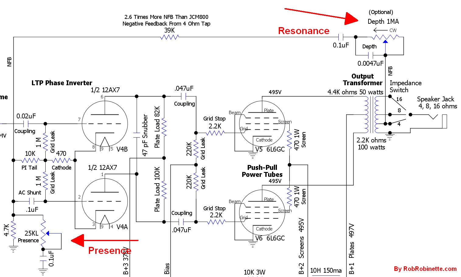
Schematic With Component Names
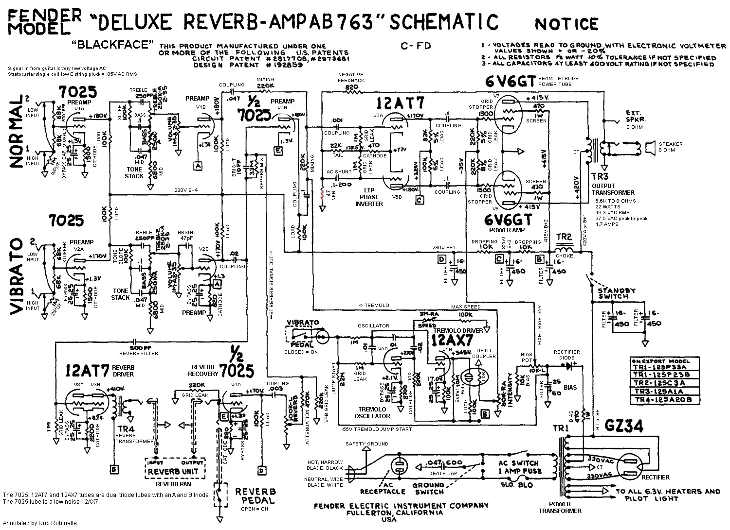
Use this schematic with all the components named for reference.
Guitar Tone & Volume Controls
Don't forget about the earliest possible place to shape the guitar tone is on the guitar itself. Adjusting the guitar's volume control can have a profound effect on touch sensitive tube amplifiers. If you are new to tube amps you need to play around with the guitar volume control to learn its effects on touch sensitivity and pick attack.
The guitar tone control affects the guitar audio signal's tone through the entire amplifier. If you are a set-and-forget guitar tone knobber try twiddling the tone control next time you're pushing the amp into heavy overdrive and notice the changes to not only the tone but the substance of the overdrive.
The tone pot and tone cap form an RC (resistance/capacitance) low pass filter which means high frequencies don't pass, they are bled to ground.
Standard Guitar Circuit
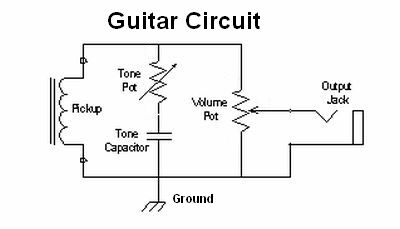
The Pickup on the left is a wire coil that generates the guitar signal. The Tone Pot sinks high frequencies to ground. It's wired as a variable resistor. Turning the Tone Pot changes the amount of high frequency signal sent to ground.
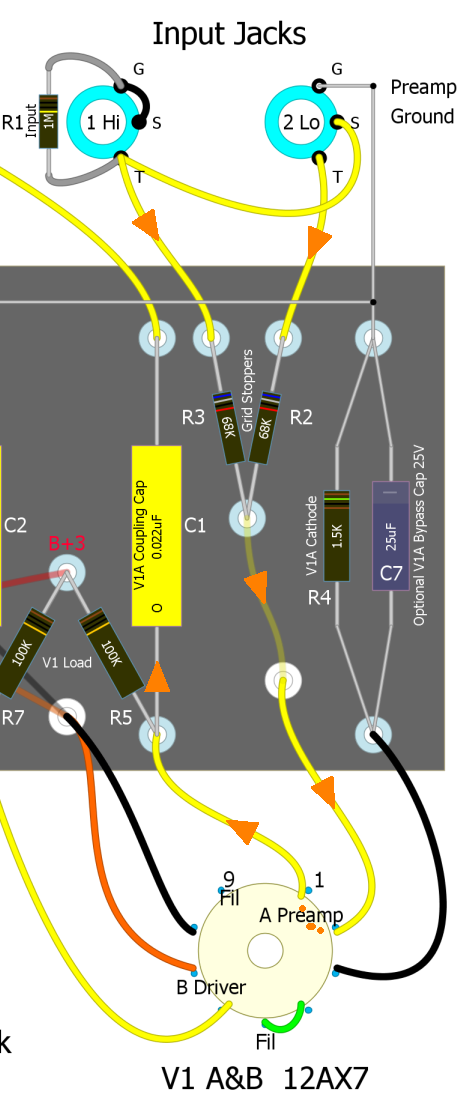
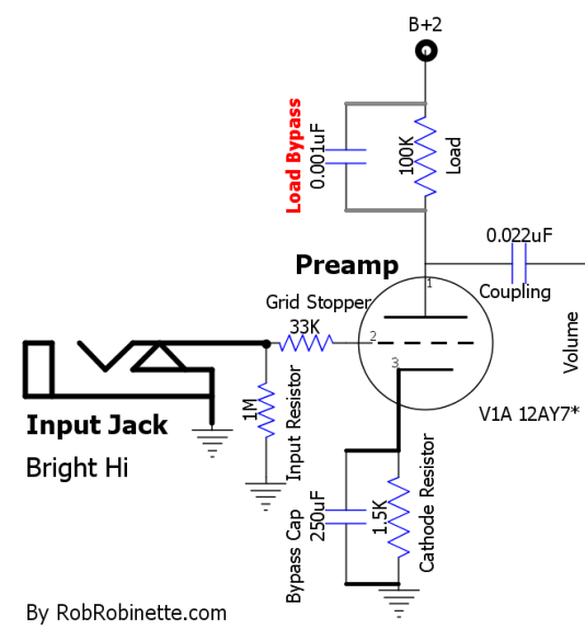
High or Low Amplifier Input
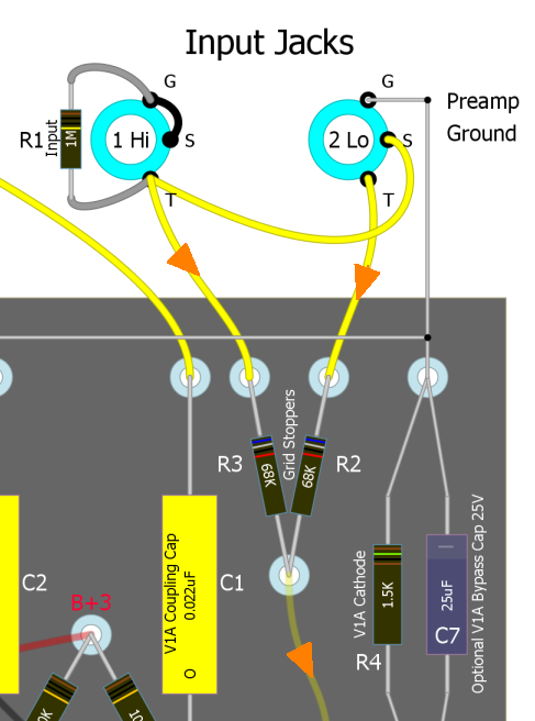
The #1 Input Hi Jack is at upper left, the #2 Low Jack (-6dB) is on the right. R1 is a 1M input resistor and set's the amp's input impedance to 1 megaohm. R2 and R3 are 68k Grid Stopper resistors that remove frequencies above human hearing and also act as mixing resistors to prevent two instruments plugged in simultaneously from interacting with one another.
For amps with Fender style "High and Low" input jacks the Low jack not only cuts the guitar signal in half (-6dB) but it also offers up a very different input impedance (136k Low vs 1M High) which can interact with the guitar pickup coils to color the tone. Humbucker and hot pickups often sound better in the Low jack. Always try both inputs with a new guitar or amp to hear which you prefer. Try both inputs during your next high octane overdrive session to hear the effect on the meat of the overdrive tone.
Power Supply Voltage Sag
Many early guitar amps from the 1950's had inadequate power supplies that would allow the amp's high voltage DC power supply to sag under high demand. Voltage sag is the dynamic voltage drop across the power transformer and rectifier that increases with current demand and creates output volume compression. Output volume compression occurs because high current demand during loud notes lowers the amps DC supply voltage and maximum volume is decreased. Conversely, low demand, quiet passages create less voltage sag and generate greater amplification. This makes loud notes quieter and quiet notes louder which equals compression.
Class A and AB amps differ in how much voltage sag is generated. Since Class A amplifiers idle near max current there are less current demand fluctuations and therefore less voltage sag. Voltage drop and sag help contribute to the warm, round, tubey sound of vintage amplifiers. For example the combination of the 5E3 Deluxe's small power transformer, low output 5Y3 tube rectifier and Class AB operation lead to metric shit tons of voltage sag.
You can simulate a tube rectifier's voltage sag by adding a "sag" resistor to a solid state rectifier's output. See Simulate a Tube Rectifier Mod for more info.
Increasing the value of the first power supply filter capacitor or adding a choke can reduce voltage sag and stiffen the power supply. They can also firm up the bottom end because it takes more power to amplify low frequencies. Keep in mind tube rectifiers have a first filter cap size limit so reference your tube rectifier's datasheet to keep from overtaxing the tube at turn-on. I'm a big fan of using a choke between the power tube plate and screen power nodes like the 5F6A Bassman and Marshall JTM45, Plexi, 2203 and JCM800 amps.
Typically high gain amps need a very clean, stiff voltage supply to prevent oscillation so voltage sag is unwanted. Many high gain amps use solid state rectifiers which do not have a filter cap size limit and their minimal voltage drop minimizes sag. It's a good idea to place no more than two triodes (one dual triode tube) per power supply node to prevent interaction and oscillation in high gain preamps.
Cathode Bypass Cap
A cathode resistor bypass cap boosts the gain of a tube amp circuit by reducing its local negative feedback by acting as an electron reservoir for the cathode. A very large bypass cap like the 250uF cap on the first cathode in the 5F6A Bassman is large enough to boost frequencies all the way down to low bass guitar frequencies. The 25uF cap on many Fender tweed (1950's) amps will boost the full spectrum of guitar frequencies. A more modest 5uF de-emphasizes the lowest guitar freqs which can tighten up the bass and prevent "farting out."
Many high gain amps use a very small .68uF bypass cap to emphasize mid and high freqs to keep the overdrive tone tight and de-emphasize low freqs that waste power and get muddy when overdriven. A smaller cap also reduces bias shift recovery time which can sweeten the overdrive tone. My "Lead Channel" mod for the 5E3, 5F6A and AB763 amps suggests the use of a .68uF bypass cap for these very reasons. You can even use a cathode bypass switch to offer up different tone shaping options.
Soldano used 1uF cathode bypass caps throughout his very high gain SLO-100 to limit low frequencies. He used relatively large .02uF coupling caps that pass the full spectrum of guitar frequencies. Most very high gain amps use a few 0.002uF coupling caps to trim & suppress low frequencies. The SLO amps do not use any 0.002uF caps. Soldano made a conscious decision to trim low end frequencies with cathode bypass cap size (partial bypass), not coupling cap size. As you can see in the graph below, low guitar frequencies are severely cut to keep the overdrive tone tight, prevent boomy lows and prevent blocking distortion.
SLO-100 1uF Cathode Bypass Cap Frequency Response
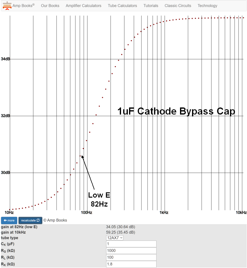
The SLO-50 and 100 preamp use several 1uF cathode bypass caps which give a partial cathode bypass. The lack of bypass for low frequencies subjects them to local NFB which not only attenuates low frequencies but helps keep them clean which limits low frequency intermodulation and harmonic distortion which can generate excessive and muddy lows. You can see that low guitar frequencies are trimmed and suppressed to keep the overdrive tone tight. Low frequencies will also push a gain stage into blocking distortion much earlier than mid and high frequencies. Soldano broke tradition and used cathode bypass cap size instead of coupling cap size to shape and control the low end.
The VHT Special 6 Ultra has a rotary "Depth" switch with 11 different selections of cathode resistor bypass capacitor for its single power tube. Changing the cathode bypass cap value of a preamp gain stage will have more of an effect on the overdrive tone than changing the bypass cap of the power tubes--of course only cathode biased power amps have power tube cathode bypass caps.
Here's an easy to use online calculator that shows the frequency response of different cathode bypass cap sizes.
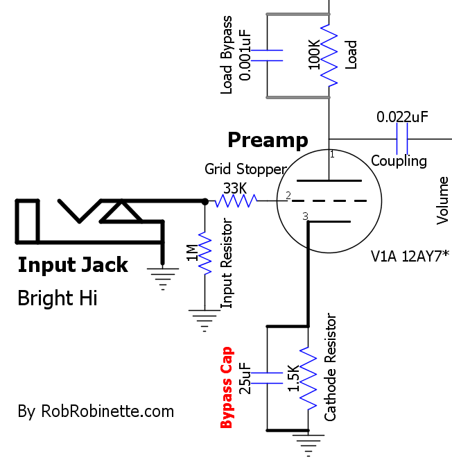
The 25uF cathode bypass cap is parallel to the 1.5k cathode resistor.
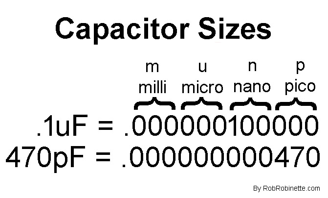
Use this chart to help convert capacitor size such as: .1uF = 100nF and 1nF = 1000pF
Tone Pot
The pot + capacitor Tone Pot is a very simple but effective way to remove high frequencies to tame an overly bright tone. The upstream impedance + tone pot resistance and tone cap form an RC (resistance/capacitance) low pass filter which means high frequencies don't pass, they are bled to ground.
This simple Tone Pot circuit puts a much lower load on the guitar signal compared to the more complex Treble Mid Bass (TMB) tone stack. The Tone Pot is usually placed early in the preamp so it can have a profound effect on the overdrive tone.
Wire the pot as a variable resistor (tie terminal 2 & 3 together) so that turning the pot up (clockwise) increases resistance: Up = more resistance = less high freqs to ground = brighter tone.
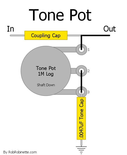
The Tone Pot sinks high frequencies to ground. It's shown shaft down (pointing away from you) and is wired as a variable resistor. Turning the Tone Pot changes the amount of high frequency signal sent to ground. An upstream Coupling Cap forms an AC voltage divider with the Tone Cap so its size and location will affect the Tone Pot's function. The Coupling Cap is also needed to keep high voltage DC out of the Tone Pot.
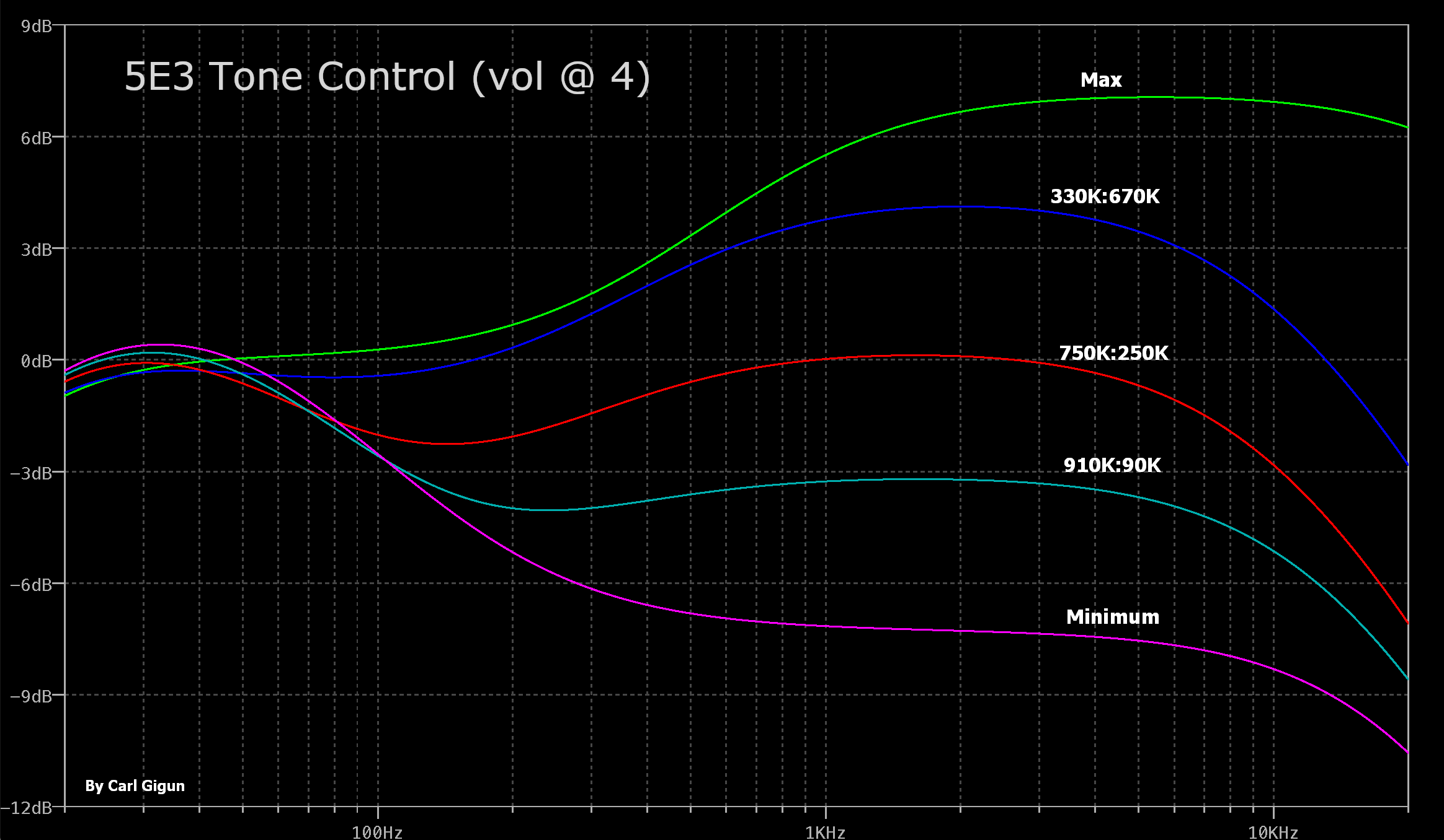
Frequency response of the 5E3 tone pot. 125K:875K means 125K of resistance above the pot wiper. The pot functions as a variable RC low pass filter. The Tone Pot function is affected by upstream impedance including the upstream signal impedance and coupling cap, downstream volume pot and volume pot bright cap. Graph and modeling by Carl Gigun.
Calculate a Filter's Frequency Cutoff
When dealing with guitar amp tone shaping circuits it's useful to be able to calculate the filter's cutoff frequency (sometimes called the corner frequency) which is defined as the frequency where the signal is cut by -3dB. The formula is simple: cutoff frequency = 1/(2πRC). R = the resistor value in ohms, C = the capacitor value in farads and π (pi) = 3.14159.
Example: 100k resistor + .0047uF capacitor RC low pass filter
1 / (2 * 3.14159 * 100,000 * .000,000,0047) = 339Hz
So 339Hz would be attenuated -3dB and frequencies above would be attenuated even more.
The formula is the same for RC low pass and CR high pass filters.
Tip: Use your calculator's inverse key 1/x and the π key to quicken this calculation.
Here's an easy to use Filter Cutoff Online Calculator.
Tone Stack
The standard TMB (Treble Mid Bass) Tone Stack is a series of three CR (capacitance-resistance) high pass audio filters and one RC (resistance-capacitance) low pass audio filter that block three bands of audio frequencies. The Treble, Bass and Mid pots change the resistance of the audio filters to alter the amount of signal filtered out. The TMB stack is a passive filter so it cannot boost any frequency band, it can only remove parts of the guitar audio signal.
The TMB tone stack can be placed early or late in the preamp. The earlier it's placed the more effect it will have on the overdrive tone.
Note the Treble pot is wired as a variable voltage divider (potentiometer) while the Bass pot is wired as a variable resistor (the input and wiper terminals are tied together). In most amps with a Mid pot it is a 10KA (audio or log) wired as a variable resistor but it may be wired as a potentiometer (input connected to the pot wiper).
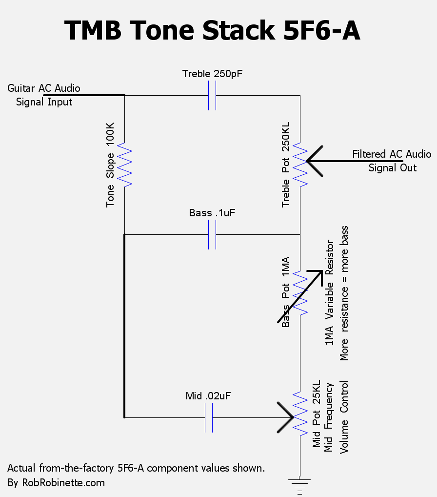
The classic Bassman Treble Mid Bass tone stack.
A common TMB mod is to change the Tone Slope (yes, that's where he got his name) resistor to a 33k, 56k, 100k, or even 150k which changes the slope of the bass-treble frequency response graph which alters the way the tone controls operate and interact. A lower value Tone Slope resistor will give you more maximum bass and less maximum treble. A higher value will give you more maximum treble and less maximum bass. High gain amps typically use a higher value tone slope to help reduce bass freqs that can cause muddy overdrive lows and blocking distortion. A higher value tone slope resistor will also lighten the impedance load of the tone stack and therefore boost gain.
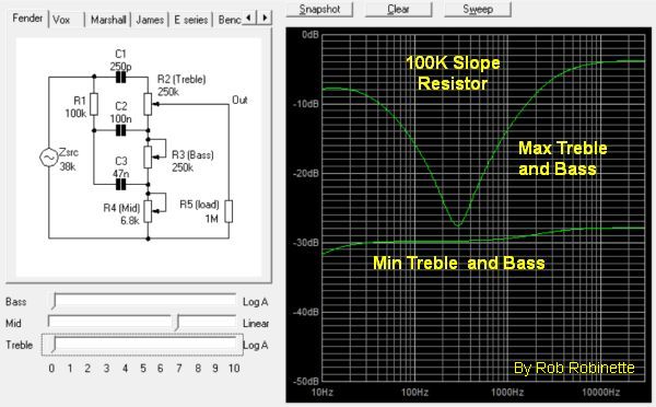
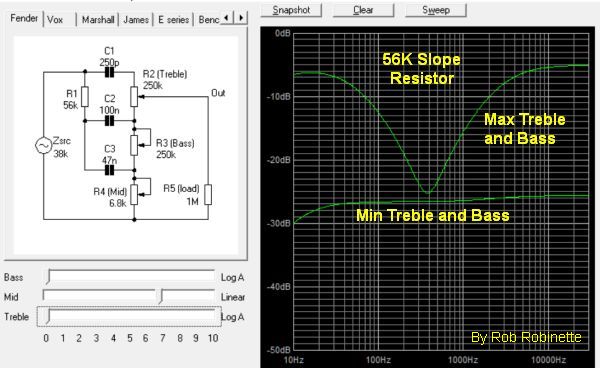
100k Tone Slope resistor on the left, 56k on the right. The effect is subtle but some prefer the 56k slope. Notice how the mid scoop is wider and the max bass and treble are balanced on the right with the 56k slope resistor. The 56k also boosts the midrange by 2.5dB. I'm a fan of the 56k tone slope resistor in low to medium gain amps.
Another common mod is changing the Tone Stack's treble tone cap. Common values are 220pF, 330pF and 470pF. A higher value will extend the treble controls reach into the mid frequencies and change the depth of the scoop.
The reissue 68 Custom Deluxe Reverb uses a .022uF Mid cap instead of the AB763 standard .047uF. You can see the difference between the .047 and .022uF Mid cap in this chart:
Tone Stack Mid Cap Change
The Custom channel's reduced .022uF middle cap shifts the "mid" frequency band higher and reduces the mid scoop by over 2dB.
The 68 Custom Deluxe Reverb also has an 18k resistor between the Bass pot and 6.8k Mid resistor. The 18k resistor works as a minimum bass setting and keeps the bass from falling off a cliff as you approach the Bass pot's minimum setting. It makes setting low bass settings easier and more precise but it does limit you to how low you can set the bass.
For more information on the TMB tone stack see How the TMB Tone Stack Works.
If you are considering modifying the tone stack I recommend you download the free Duncan Amps Tone Stack Calculator so you can see graphically what the modifications do and how the Treble and Bass pots will react to the new component values.
Duncan Amps Tone Stack Calculator
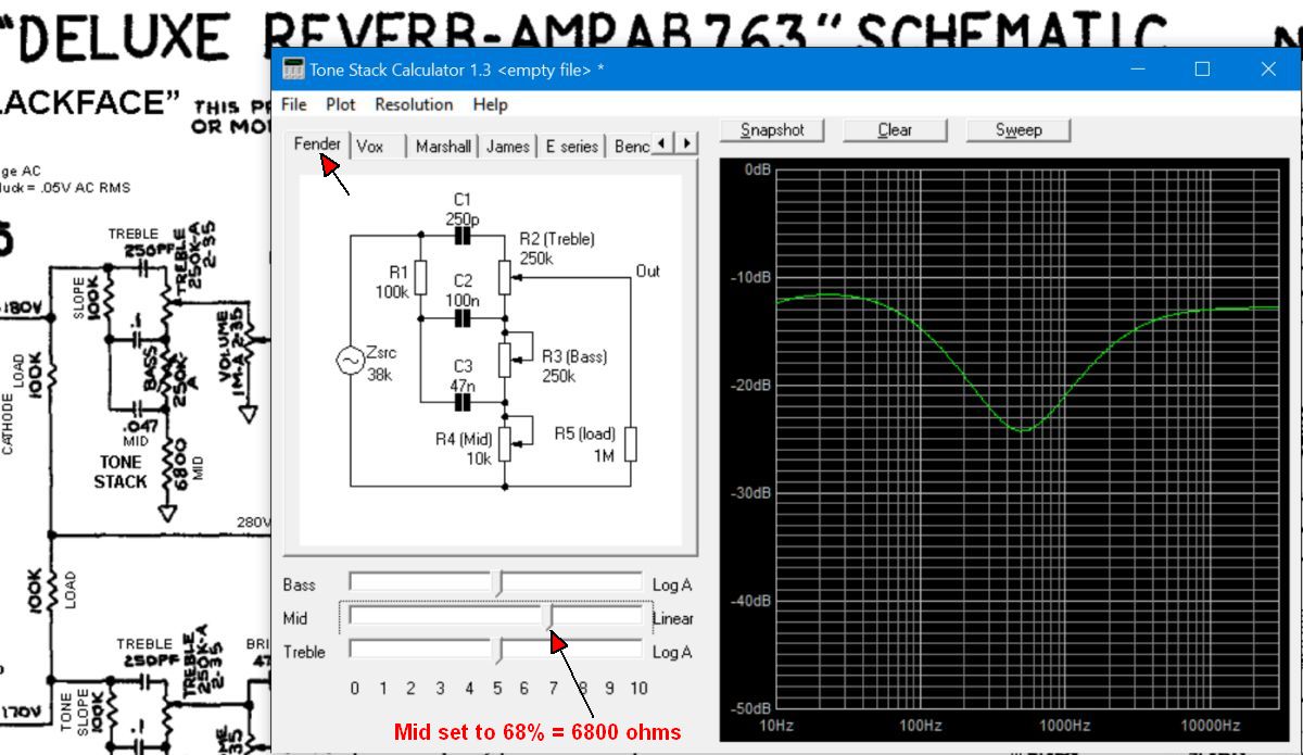
After installing the Tone Stack Calculator, click on the Tone Stack Calculator's "Fender" tab at upper left. By setting the Mid slider (bottom left) to 68% you get 6800 ohms to equal the Deluxe Reverb's fixed 6800 ohm Mid resistor. You can double-click any component in the tone stack schematic to change its value so it's easy to see what happens to the control movements when you change the 100k slope resistor to 56k or adjust the value of the Mid resistor. The frequency response graph on the right will change as you alter component values or move the Bass and Treble pot sliders (at bottom left). Just playing with the pot sliders and watching the graph will tell you a lot about the interactive nature of the TMB (treble mid bass) tone stack. The Tone Stack Calculator is a very cool tool.
If you do install the Tone Stack Calculator be sure and check out how a 25KL and 100KL Mid pot can act as a "Raw" control and boost the signal compared to a 6.8k resistor or 10KA pot.
Tone Stack Bypass or "Raw Switch"
This is a great mod for pretty much any amp with a TMB (treble mid bass) tone stack. Because this type of tone stack really loads down the guitar signal being able to eliminate the tone stack is a valuable option. Just add an SPST ON/OFF mini-switch to the Mid pot's (or 6.8k Middle tone resistor's) ground. No ground = no tone stack which gives you a very significant signal boost and pure "raw" unaltered tone. The raw tone has a non-scooped mid similar to the no-tone-stack tweed amps such as the 5E3 Deluxe. It also works great with EQ pedals because it lets the pedal do all the tone shaping.
Raw Switch On and Off
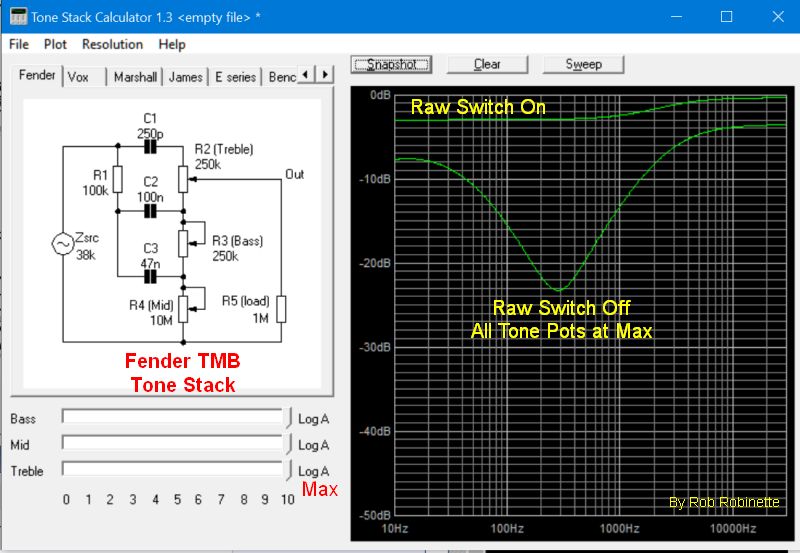
You can see how even with all three tone pots at max what a huge boost in signal you get when the Raw Switch is opened (tone stack ground disconnected). The mid scoop is also flattened out. Chart is from the Duncan Tone Stack Calculator.
If the raw signal boost is too much for you, you can tune the amount of signal boost and mid scoop by placing a resistor across the raw switch terminals. Temporarily alligator clip a 24k or 47k resistor to the switch terminals and tune the resistor value to taste.
The larger the resistor, the shallower the mid scoop with more signal boost.I placed my Raw mini-switch between the Treble and Bass pots.
Bass Tone Control
This is a simple Bass Tone Control. As you turn the pot down it removes bass frequencies. It uses a very small mica cap in line with the audio signal which strips out low frequencies. A 1MRA (1 megaohm reverse audio or anti-log) pot wired as a variable resistor gives you a variable cap bypass. As you turn the Bass pot up (clockwise) less signal goes through the cap and less bass is cut. At full up (clockwise pot rotation) the cap is fully bypassed so all frequencies pass around the cap and normal, full frequency amp tone is passed. Run the control at full up (full clockwise) for normal, full frequency tone because at full bypass the Bass Tone Control circuit disappears.
The corner frequency of the Bass Tone Control changes with signal impedance but the 500pF cap will work at most places in the amp circuit. A high impedance signal will pass lower frequencies through the cut cap so if you need more control authority then reduce the cap size to 250 or even 100pF.
The Bass Tone Control circuit cannot be used as a coupling cap (blocking cap) because the pot will allow DC to pass. The Bass Tone Control must be placed downstream of a coupling cap to keep DC out of the pot.
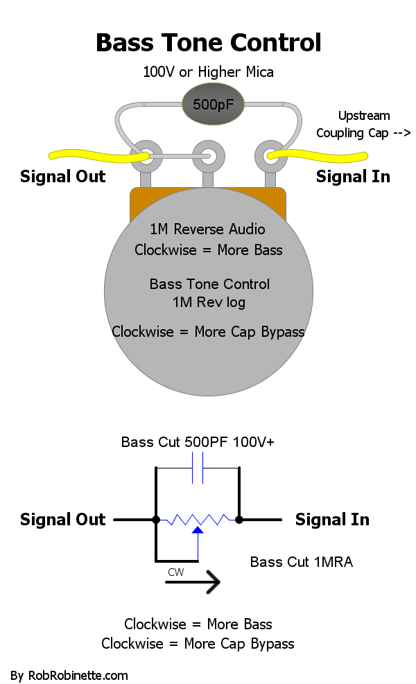
The Bass Tone Control circuit is a small value cap with a variable bypass. More bypass gives you more bass, fully bypassed (full clockwise rotation) gives you a normal, full frequency signal. The mica cap should be rated for 100v or higher. Download the pdf here and the DIYLC file here.
Bass Cut Control
This control is the opposite of the above Bass Tone Control. As you turn the pot up it reduces bass. It uses the same very small mica cap in line with the signal which strips out low frequencies. A 1MA pot wired as a variable resistor gives you a variable cap bypass. As you turn the Bass Cut pot up (clockwise) more signal goes through the cap and more bass is cut. At full down (counter-clockwise pot rotation) the cap is fully bypassed so all frequencies pass around the cap and normal, full frequency amp tone is passed. Run the control at full down (full counter-clockwise) for normal, full frequency tone because at full bypass the Bass Cut circuit disappears.
The corner frequency of the Bass Cut Control changes with signal impedance but the 500pF cap will work at most places in the amp circuit. A high impedance signal will pass lower frequencies through the cut cap so if you need more control authority then reduce the cap size to 250 or even 100pF.
The Bass Cut Control circuit cannot be used as a coupling cap (blocking cap) because the pot will allow DC to pass. The Bass Cut Control must be placed downstream of a coupling cap to keep DC out of the pot.
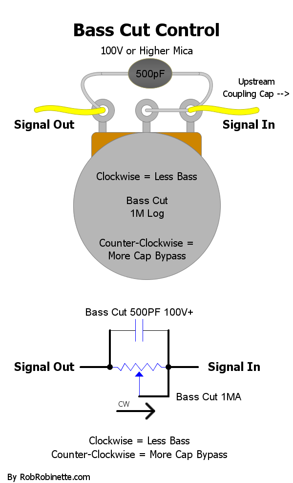
The Bass Cut Control circuit is a small value cap with a variable bypass. Less bypass gives you less bass, fully bypassed (full counter-clockwise rotation) gives you a normal, full frequency signal. The mica cap should be rated for 100v or higher. Download the pdf here and the DIYLC file here.
Bright Caps
Bright Caps are placed around Volume pots, Gain pots and Mixing, Attenuator and Grid Stopper resistors. They allow high frequencies to bypass the resistance. On pots they can keep the tone from getting dark at low volume settings. On resistors a bright cap can act as a treble peaker to enhance the high end by allowing high frequencies to go around the resistance.
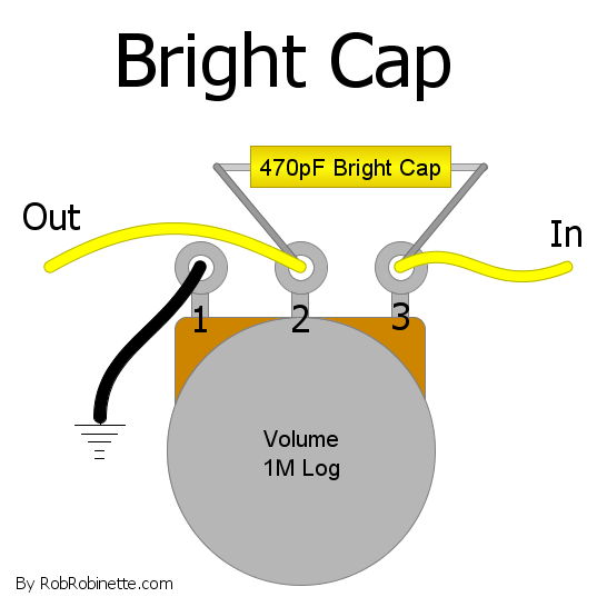
Bright cap on a volume pot.
Bright Caps on volume and gain pots become more noticeable as you turn down the pot but at maximum volume the bright cap does nothing because there is no resistance to bypass.
Reducing the cap value raises the
filter frequency and increasing the value lowers the frequency. Changing the cap size does not affect the amount or volume of bypass, it only changes the cutoff frequency. You can add a 100k to 330k resistor in series with a bright cap to reduce the amount or volume of high frequency signal passing through it.To bypass a volume or gain pot with a bright cap you connect the cap's two leads to the pot's input and output terminals as shown above.
Here's a Volume Pot Bright Cap calculator.
Sometimes removing a bright cap can help you find the tone you're after. For Fender black and silverface amps try clipping the 10pF bright cap around the 3.3M Reverb Mix resistor to mellow the highs from the Vibrato Channel. Clipping the bright cap on the Vibrato Channel's volume pot is also a very common blackface amp mod.
Coupling Caps
Coupling caps
(sometimes called blocking caps) are used to AC couple two amplifier stages together. They block DC voltage and current but allow the AC guitar signal voltage to pass. They also act as high pass filters so you can use them to trim unwanted low frequencies. The larger the value of the coupling cap the lower the bass floor (cutoff frequency) so the deeper the amp's voice. Reduce the value of a coupling cap and you will raise the bass floor and thin the tone. Raising the bass floor can tighten bass response and clean up the overdrive tone by removing muddy bass.The 5E3 Deluxe is known for having flabby, loose bass and a common mod is to reduce the size of its huge .1uF coupling caps down to .047 or even .022uF.
Capacitor C1 is a coupling cap. It blocks the high voltage DC on V1's plate (pin 1) and keeps it out of the volume control.
Coupling cap size can have a profound impact on an amp's overdrive tone because a smaller coupling cap can reduce the severity of blocking distortion. The Fender 5E3 Deluxe uses massive .1uF coupling caps while the high gain Marshall Plexi uses a tiny .0022uF cap to control blocking distortion and limit very low frequencies to keep the overdrive tone tight on the Bright or Lead channel. My "Lead Channel" mod for the 5E3, 5F6A and AB763 amps suggests the use of a .0047uF coupling cap for these reasons. To learn more about how coupling cap size affects overdrive see Guitar Tube Amp Overdrive.
Here's an online Coupling Cap Calculator.
Here's another online calculator for the coupling cap between the phase inverter and power tubes that controls the Phase Inverter Bass Response.
Voltage Dividers
High gain amps walk a fine line between sonic bliss and complete mayhem. Amp designers use voltage dividers to carefully control signal level to keep the tone sweet and prevent over overdrive. Usually the best overdrive tone is accomplished when several preamp stages go into overdrive simultaneously. We can make that happen by "throttling" the guitar signal at each stage with voltage dividers.
Classic Voltage Divider
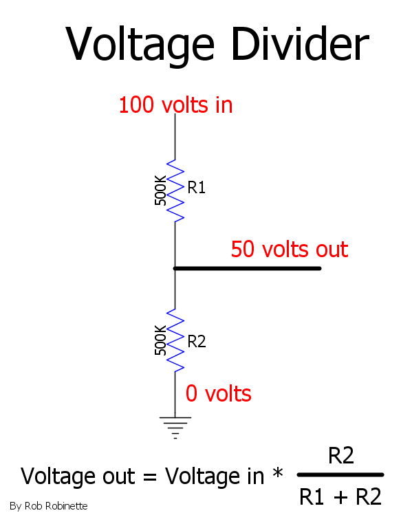
Note how there are 100 volts at the top of the resistors and 0 volts at the bottom (ground). The upper resistor is R1 and the lower is R2.
A voltage divider literally divides voltage. Take a look at the diagram above. We have two 500k resistors with 100 volts at the top and 0 volts (ground) at the bottom. If we tap the resistors at the top we get 100 volts, tap the resistors at the bottom and we get 0 volts. Now if we tap the resistors at the middle, half way down at 500k, we will get half the voltage, 50 volts. Tap higher and the voltage moves toward 100v, tap lower and the voltage goes down toward 0 volts.
Note the equation at the bottom of the diagram. The formula to calculate the voltage out of a voltage divider is: resistance below the resistor split / total resistance or R2 / (R1 + R2).
We can calculate the voltage out of the voltage divider by multiplying the Voltage in * R2 / (R1 + R2). For our voltage above we get: 100v * 500,000 / (500,000 + 500,000) = 100v * .5 = 50 volts out. The R2 / (R1 + R2) determines the ratio of the upper to lower resistor. If you make the lower resistor smaller more voltage will be bled to ground so you will have less voltage out.
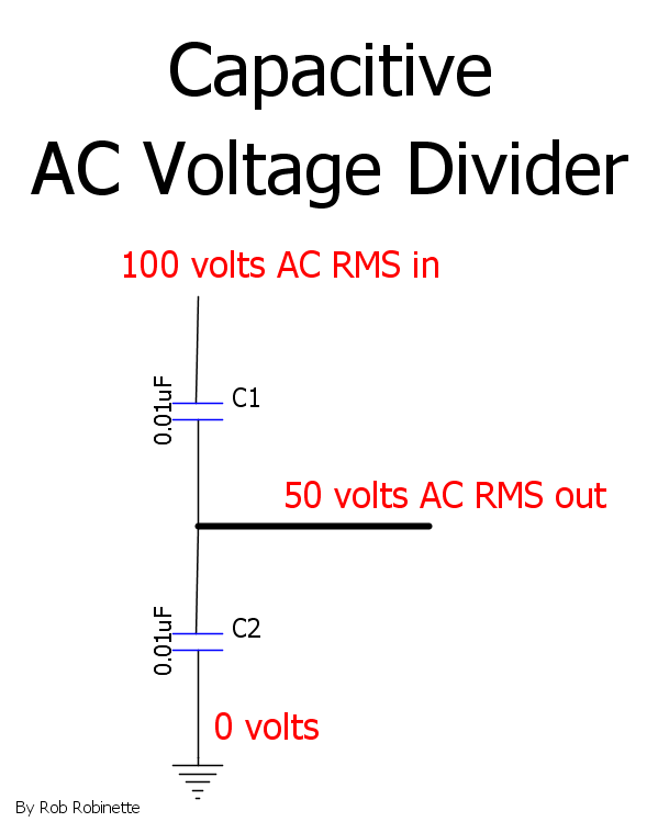
Resistance based voltage dividers work the same with AC or DC voltage but we can put two capacitors in the same configuration as the R1 and R2 resistors above and form a capacitive voltage divider that divides AC voltage. The capacitors block DC voltage and current so only AC voltage is divided and passed downstream.
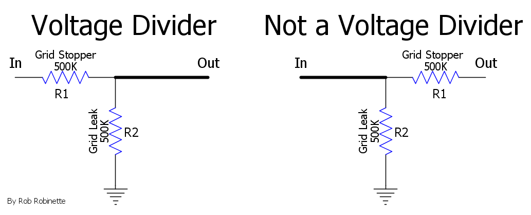
Note how the placement of the upper resistor is important. The circuit on the right is not a voltage divider.
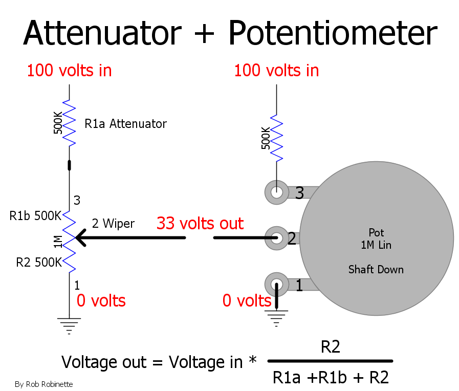
An attenuator resistor (R1a 500k) is added to a volume pot to reduce max volume. The R1a resistance is added to the pot's "above the wiper" resistance so it adds attenuation (cuts the max guitar signal out). With the pot set to the mid point with 500k + 500k above the wiper and 500k below the wiper gives us a 66% cut in the guitar signal compared to a 50% cut without the attenuation resistor. With the pot set to max the attenuator resistor will still cause a 33% cut in guitar signal. This simple circuit can be used in high gain preamp circuits to dump excessive gain. If needed, a bright cap (treble peaker) can be placed in parallel with the attenuator resistor to allow high frequencies to go around the divider and boost the highs. The formula to calculate the voltage out is the same as a voltage divider: resistance below the wiper / total resistance.
Voltage Divider Bright & Dull Caps
High gain amps employ voltage dividers in the preamp to control signal level. If you place a
bright cap across the first resistor in the divider pair (the Attenuator) you will brighten the tone by allowing high frequencies to bypass the voltage divider. This bright cap is often called a Treble Peaker. A Treble Peaker cap acts as a semi-active high frequency boost. In the voltage divider below the guitar signal is cut in half except for high frequencies--they go around the divider and are not cut so in effect high frequencies above the bright cap corner frequency are doubled in volume compared to the rest of the guitar signal. Treble Peakers are used in all high gain tube guitar amplifiers to give the amp high gain sizzle. The Marshall JCM800 uses two 470pF Treble Peakers. The Soldano SLO-100 uses a .002uF Treble Peaker in the Overdrive Channel and a tiny 120pF in the Clean Channel.
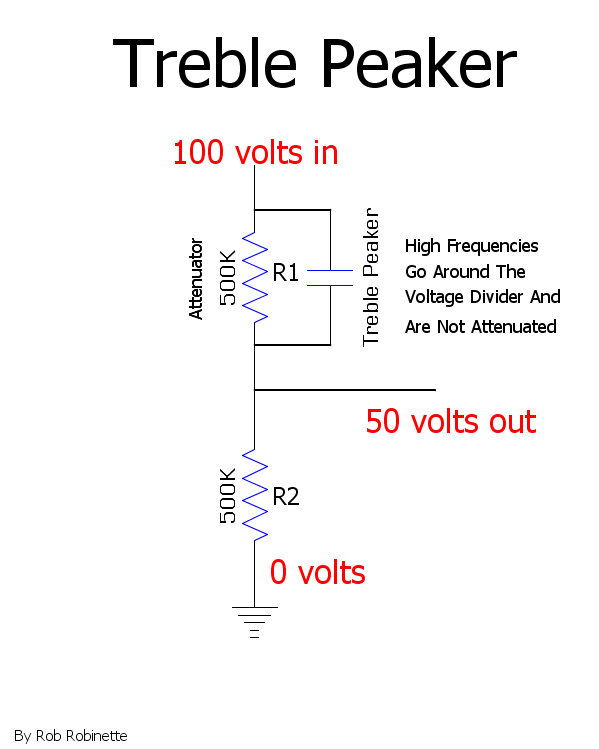
The Treble Peaker cap allows high frequencies to go around the upper resistor so they are not cut.
Here's an online Grid Stopper Calculator to calculate the frequency cutoff of a Treble Peaker.
If you place a cap on the second resistor (the one connected to ground) you will bleed high frequencies to ground creating a "Dull Cap."
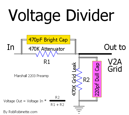
This voltage divider is located between V1A and V2A in the Marshall 2203 (minus the Dull Cap). With two 470k resistors this divider cuts the guitar signal in half (-6dB). Note the "Dull Cap" around resistor R2. You wound never need to employ both a Bright and Dull Cap on a single voltage divider as shown above.
You can place a Dull Cap across any grid leak resistor to remove high frequencies.
Here's an online Grid Stopper Calculator to calculate the frequency cutoff of a Bright Cap across a Grid Stopper resistor.
Preamp Plate Load Resistor Bypass Caps
You can remove some high frequencies by placing a
50pF to 1000pF (.001uF) "Dull Cap" around a preamp plate load resistor. This can be used in high gain amps to help control oscillation by removing unneeded very high freqs above human hearing. It can also be used to reduce ice pick highs. The B+ power supply on the hot side of the plate load resistor is seen as an AC signal ground so high frequencies on the plate pass around the plate load resistor to "ground."Here's an online Plate Load Resistor Bypass Cap Calculator.
.001uF Load Bypass "Dull Cap" in parallel with the V1A 100k plate load resistor.
Preamp Local Negative Feedback
This mod is an extremely easy to add local negative feedback loop that can be used to tune the overdrive tone of any high gain preamp. The feedback is negative because the plate is 180 degrees out of phase with the grid. The mod connects a preamp's second
, third or fourth gain stage plate back to its grid through a 470k to 44M resistor and .047uF (400v or higher) cap.
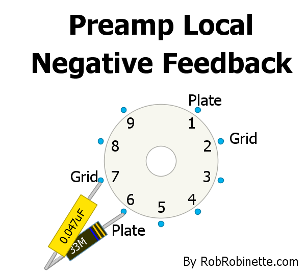
A
470k to 44M resistor and .047uF 400v+ cap connect the preamp grid and plate together to form a local negative feedback loop. The mod can also be used on the "A" triode pins 1 and 2.Like most amplifier negative feedback loops this mod will reduce distortion, tighten the transition from clean to dirt and slightly reduce gain.
It can also be used to fine tune the gain in a high gain preamp instead of simply using preamp voltage dividers to attenuate the guitar signal.At first blush I was going to recommend not using this mod on the first stage of amplification because if the cap fails as a short it could inject high voltage into the guitar circuitry but even if this does happen the large value feedback resistor will limit the current to 18 micro amps (.018 milliamp) or less so it's not a concern. This mod would be of relatively little use in the first gain stage anyway since it is rarely overdriven.
If this NFB loop tightens up the tone too much try a larger value resistor
up to a massive 44M. The larger the resistor the less negative feedback gets through to the grid. This is a pretty cool yet extremely simple circuit that should be experimented with in all high gain preamps.Cold Clipper Gain Stage
The cold clipper
gain stage is a very useful tool for voicing an amp's overdrive tone. It is used in many high gain tube amps to generate early and smooth sounding overdrive tone.For minimum distortion a tube should be biased halfway between cutoff (when all electron flow is stopped) and saturation (when electron flow is maxed out). A 1.5k cathode resistor for a typical tube amp 12AX7 triode gain stage is very close to center bias.
A cold clipper's very large 10k to 39k cathode resistor sets a cold bias that leaves little room on the shutoff side so the input guitar signal can easily be clipped when the signal's negative lobe on the grid reduces electron flow through the tube and electron flow is shutdown completely. This clipping is asymmetric because there's plenty of room on the saturation side of the bias point. The saturation side of the signal isn't distorted and carries the original musical content. Asymmetric clipping is heard as softer and creamier than symmetric clipping (top and bottom of the wave clipped). Asymmetric clipping is full of sweet sounding even order harmonics and minimizes nasty sounding odd harmonics.
The Marshall JMC800 uses a cold clipper stage with an unbypassed 10k cathode resistor. Soldano liked to use a 39k cathode resistor for his cold clipper.
The cold clipper's asymmetric output signal can also be clipped in later gain stages at high volume levels. Asymmetric clipping tends to sound smoother and creamier than symmetric clipping where both the + and - signal lobes are clipped equally. With asymmetric clipping one lobe carries the clean signal while the clipped lobe carries the distortion. The cold clipper generates early, relatively low volume, smooth, musical preamp distortion that can be controlled by a master volume for high gain tone at lower volume. As the cold clipper distortion comes on it blends seamlessly into the downstream phase inverter and power tube distortion into a cacophony of delicious high gain tone. A cold clipper stage is a great way to enhance an amp's overdrive tone.
If your amp's preamp is not high gain you will probably need to use a clean boost pedal to get the cold clipper working.
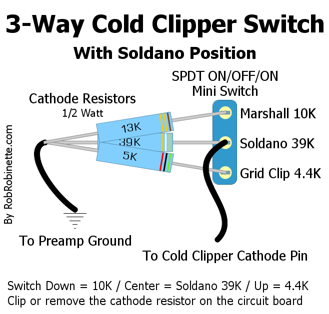
You can put a cathode bypass cap around the 4.4k resistor to boost the "Clean" setting.
The cold clipper is also a relatively low gain stage compared to one with a fully bypassed cathode. Soldano used the cold clipper cathode resistor value to trim gain to make his preamp work as desired. The higher the resistance value the lower the gain. That's one of the reasons he used a very large 39k cathode resistor in his cold clipper.
You can use a switch to select a "normal" 1.5k or cold clipper 10k cathode resistor.

A Note About Negative Feedback
Many of the following late-in-the-circuit tone tweaks are inside the typical negative feedback loop which feeds the signal from the speaker jack back into the phase inverter (or driver in single-ended amps). The NFB circuit will "fight" tone tweaks and try to remove their effects. For amps with heavy NFB you're best off adjusting the NFB circuit itself (like the Presence and Resonance Controls and Ice Pick Cap).
Phase Inverter Plate-to-Plate Snubber
Sometimes called a "fizz cap" the snubber is typically 47pF to 100pF. It connects the two phase inverter plates with a capacitor to remove very high "ice pick" frequencies. In a push-pull amp the guitar audio signals on the two phase inverter plates are 180 degrees out of phase with one another so mixing the two signals together nullifies the signal, kind of like mixing matter and antimatter. The snubber also aids amplifier stability. If your amp already has a phase inverter plate snubber you can increase its size to trim ice pick highs and overdrive fizz. You can temporarily alligator clip a second cap across the installed snubber to find the total value that works for you. This is a late tone tweak which doesn't affect preamp distortion.
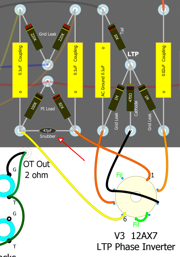
Red arrow points the the 5F6A Bassman's 47pF phase inverter plate snubber cap.
Presence Control is
a Late Semi-Active HF BoostThe Presence Control is a variable low pass filter which removes high frequencies in the negative feedback circuit. Removing high frequencies from the NFB circuit acts to boost high frequencies at the speaker. Not only are the high freqs boosted but with the reduction of NFB they become "harrier" with added harmonic distortion. Turn down the Presence Control to reduce overdrive fizz and ice pick or to subtly tweak your tone.
Overdrive fizz and ice pick highs are typically caused by harmonic and intermodulation distortion added by the overdriven stages in the amp--after the tone controls. Using an early-in-the-circuit tone control to remove fizz and ice pick will sometimes smother the tone because so much harmonic content is lost. A late-in-the-circuit tone control like the Presence Control or Ice Pick Cap can usually remove the fizz and ice pick without killing the overdrive tone's fullness and sparkle.
You can also thicken up your clean tone by turning up the presence control to add high frequency harmonics. As a general rule the harder you push an amp the lower the presence control should be set.
The Presence Control affects only the components inside the NFB loop witch is typically the phase inverter and power tubes.
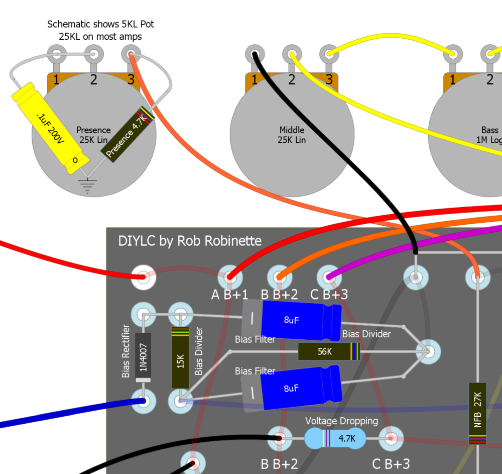
Presence Control (bottom left) bleeds high frequencies from the negative feedback signal to boost high frequency output and add high freq harmonic distortion (add some hair). As you turn the control clockwise (up) the wiper moves downward on the schematic.
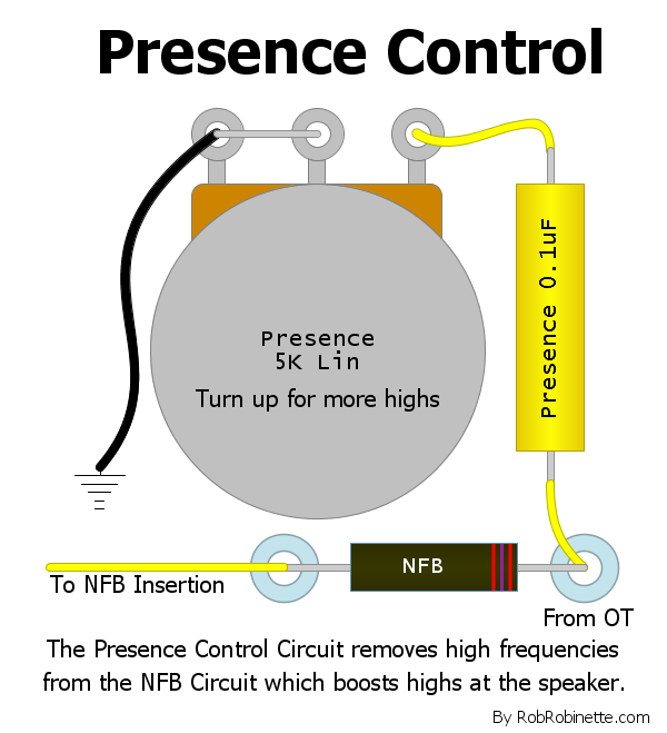
Generic Presence Control circuit. The Presence cap sends high frequencies to ground. The Presence pot varies how much high frequency signal is sent to ground. Removing high frequencies from the negative feedback circuit boost highs at the speaker. Placing the cap on the output transformer side of the NFB resistor will give best control authority.
5F6A Bassman Presence Control
Terminal 1 and 2 of the Presence Pot (upper left) are connected to the 0.1uF Presence capacitor which is connected to ground. Terminal 3 is connected to the NFB circuit. The 0.1uF Presence cap keeps DC voltage out of the Presence pot. This presence circuit is installed in most original 5F6A Bassman and JTM45 amps.
The 4.7k resistor found on many 5F6A Bassman amp presence pots cuts the total presence resistance to 4k (25k pot in parallel with 4.7k resistor). The added resistor also quickens the action of the presence control by changing the pot's taper from linear to slightly logarithmic. The reduced presence resistance also adds to the phase inverter's gain by reducing "tail resistance". More importantly, the 27k NFB resistor and 4K presence resistance form a voltage divider for the NFB signal so cutting the presence resistance by 20% also cuts the 5F6A's negative feedback by 20% which would thicken the clean tone and slow the already lazy transition from clean to dirty tone. This circuit change makes the difference in negative feedback levels between the 5F6A and the Marshall JTM45 even greater. The JTM45 has 2.8 times more negative feedback than the original 5F6A but has 3.4 times more NFB than a 5F6A with the 4.7k presence resistor across the 25k Presence pot.
Resonance Control is Another Late Semi-Active Tone Control
The Resonance Control does for low frequencies what the Presence Control does for highs. The Resonance Control blocks the flow of low frequencies in the negative feedback circuit. Blocking low frequencies from the NFB circuit acts to boost those low frequencies at the speaker. Not only are the low freqs boosted but they become "harrier" with added harmonic distortion. The bass response also becomes audibly "looser" due to less speaker damping. Use the Resonance Control to subtly tweak your amp's low end.
You can also thicken up your clean tone by turning up the resonance control to add low frequency harmonics. As a general rule the harder you push an amp the lower the resonance control should be set.
The Resonance Control, like the Presence Control above, affects only the components inside the NFB loop witch is typically the phase inverter and power tubes.
For most Resonance Control authority place it on the output transformer side of the NFB resistor (39k resistor top center in schematic below).
Resonance Control (upper right) blocks low frequencies from the negative feedback signal to boost low frequency output, add low freq harmonic distortion (add some hair) and loosen the bass response. The 0.0047uF cap is a low frequency blocking cap and the Resonance pot bypasses the blocking cap allowing NFB low frequencies to go around. As you turn the control clockwise (up) the wiper moves in the direction of the arrow on the schematic. I recommend you place the resonance circuit on the transformer side of the NFB resistor. Soldano called the resonance control, "Depth control."
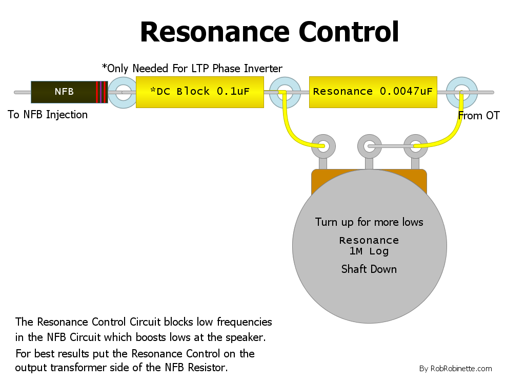
Generic Resonance Control. If the amp has a Long Tail Pair (LTP) phase inverter then the .1uF DC Block capacitor is needed to keep DC voltage out of the Resonance pot.
Ice Pick Cap
This is a subtle, very late tone tweak that can be temporarily clipped onto the negative feedback resistor to tweak to taste. This is a great way to cure ice pick highs and reduce overdrive fizz. The cap allows high frequencies to go around the negative feedback resistor which reduces high freqs at the speaker. In other words more high frequency NFB is added. The cap can be anything from 47pF up to 500pF. The cap size affects the roll off frequency but not the amount or volume of highs. You can add a resistor in series with the cap to reduce the volume of high freqs that pass through the cap. The Ice Pick Cap affects only the phase inverter and power tubes.
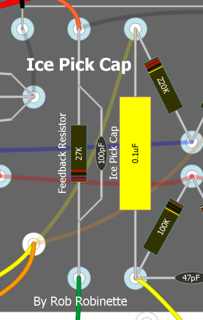
100pF "ice pick cap" paralleling the negative feedback resistor in the 5F6A Bassman.
Intentional Phase Inverter Mismatch
Howard Dumble added a phase inverter balance control to his Tweedle Dee tweed Deluxe amplifier. The control allows intentional mismatch between the two phase inverter output signals which generates sweet sounding even order harmonic distortion and intermodulation distortion to fatten up the amp's tone. Anytime harmonic distortion is created intermodulation is also created. The phase inverter balance control lets you thicken your clean tone but also maintain control when pushing the amp hard into overdrive.
Howard Dumble Tweedle Dee & 5E3 Deluxe Differences
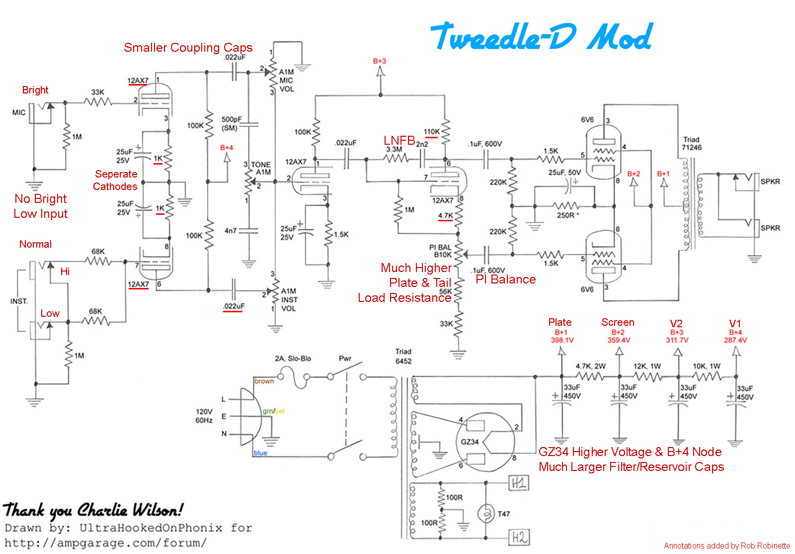
I have highlighted the differences between the Tweedle Dee and a standard Fender 5E3 Deluxe with red text. The phase inverter balance pot (PI BAL 10K linear pot) is shown at center.
Intentional Power Tube Bias Mismatch
Adding imbalance between the power tubes increases sweet sounding second order harmonic and intermodulation distortion.
Adding a balance pot to a fixed bias amp's bias circuit allows you to adjust the bias and balance the bias between the power tubes. This allows you to use unmatched tubes but bias them evenly. You can even run a 6V6 and a 6L6 power tube together and bias each tube properly. You can also fatten up the clean and overdrive tone by intentionally mismatching the two tubes' bias which increases sweet sounding even order harmonic distortion. An increased bias mismatch can cause an increase in hum so keep an ear out for that if you dial up an intentional power tube mismatch.
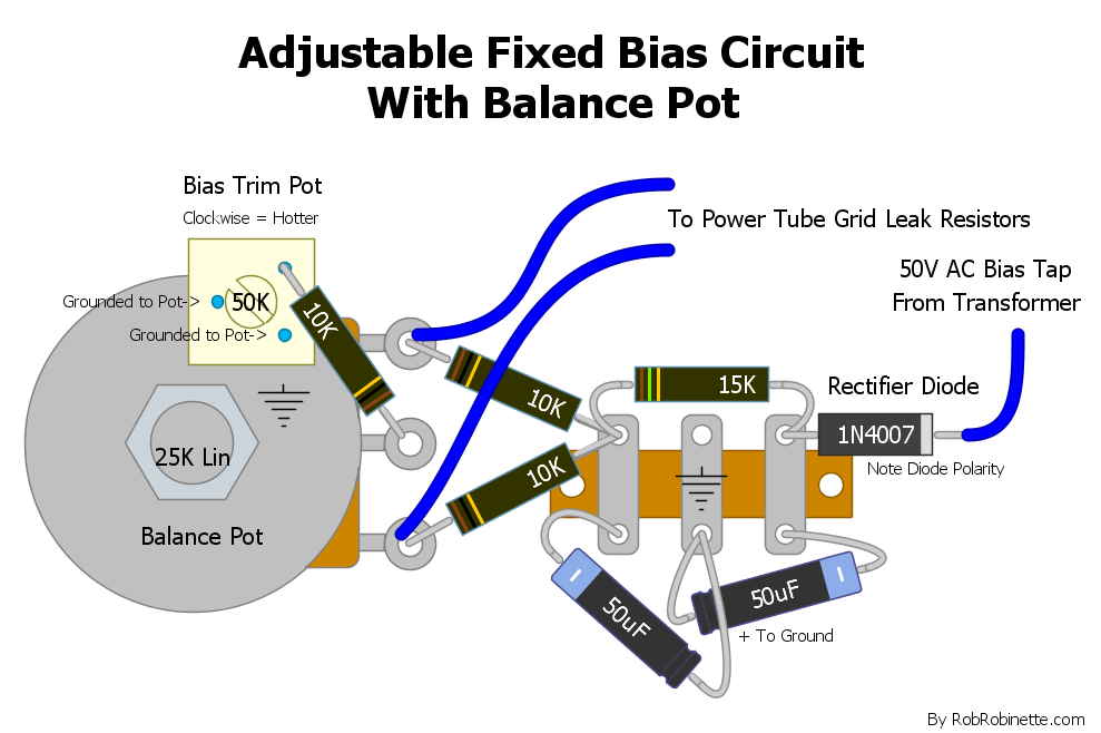
The 50k Bias Trim Pot sets the bias and the Balance Pot balances the current between the two power tubes.
VOX Cut Control
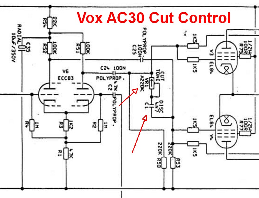
The VOX Cut Control connects the power tube grids with a 250k audio pot and 4.7nF (.0047uF, 200v or higher) capacitor to allow variable high end cut. In a push-pull amp the guitar audio signals on the two power tube grids are 180 degrees out of phase with one another so mixing the two signals together nullifies the signal.
I'm a big fan of this very late tone tweak because it pairs well with an early tone control or stack. Use the early tone control to get the overdrive tone and substance you want then use the Cut Control to fine tune the tone and trim fizz and ice pick highs. The Cut Control affects only the power tubes.
Wire the cut pot as a variable resistor so that as you turn the knob up (clockwise) resistance increases. Up = more resistance = brighter tone.
The VOX AC30 that this Cut Control is taken from does not have a negative feedback loop. An amp's negative feedback loop will "fight" the cut control so this tone control works best with amps with light or no NFB.
220KA or 250KA pot (audio pot wired as variable resistor) and .0047uF 200v cap connect the two phase inverter outputs.
Cut Control Mod on 5F6A Bassman
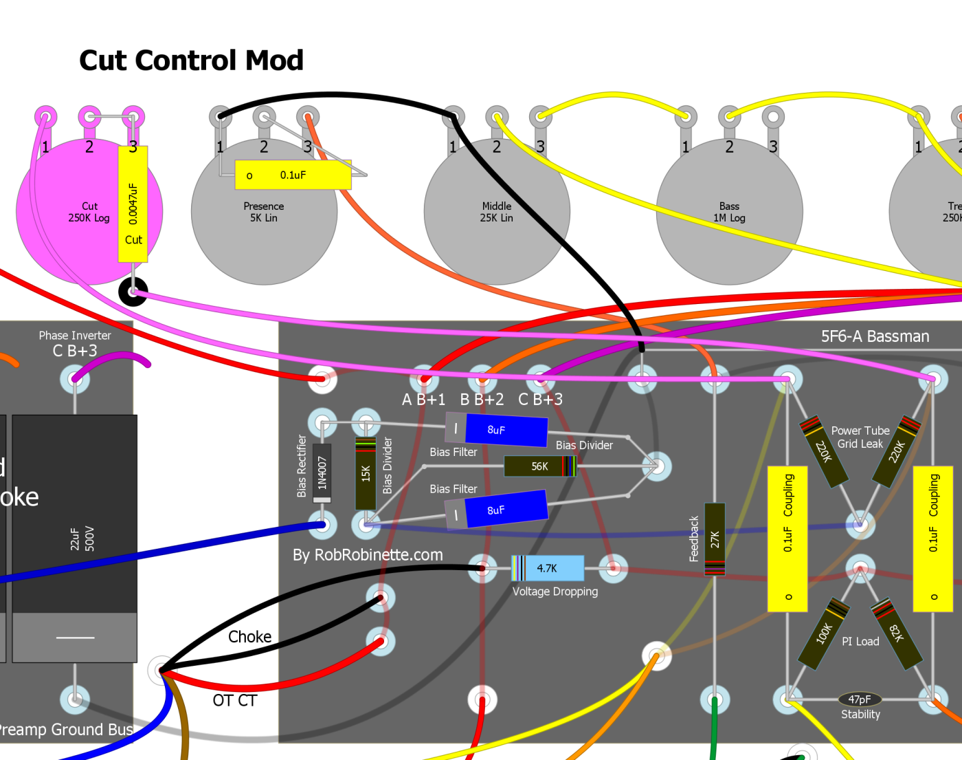
The .0047uF Cut Cap can be supported by a terminal strip.
The cut control capacitor limits the cut effect to high frequencies but if you jumper around the cap the pot becomes a Trainwreck Type-3 Master Volume.
RobRob Master Volume / Cut Control with Pull Pot
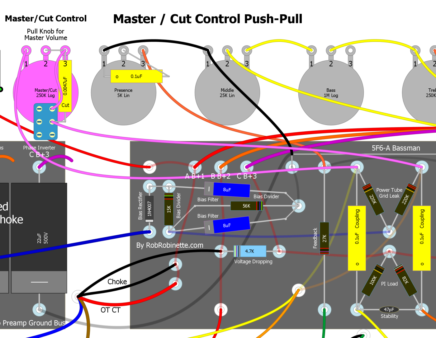
You can turn a Cut Control into a Trainwreck Type 3 Master Volume by simply jumpering around the Cut Cap. I use a push-pull 250k audio (log) pot to select either the Master Volume or Cut Control. Pull the Cut Control knob up to select the Master Volume. With the knob down the Master Volume is completely removed from the circuit. This is a very cool and useful mod.
RobRob Master Volume / Cut Control Switch Mod
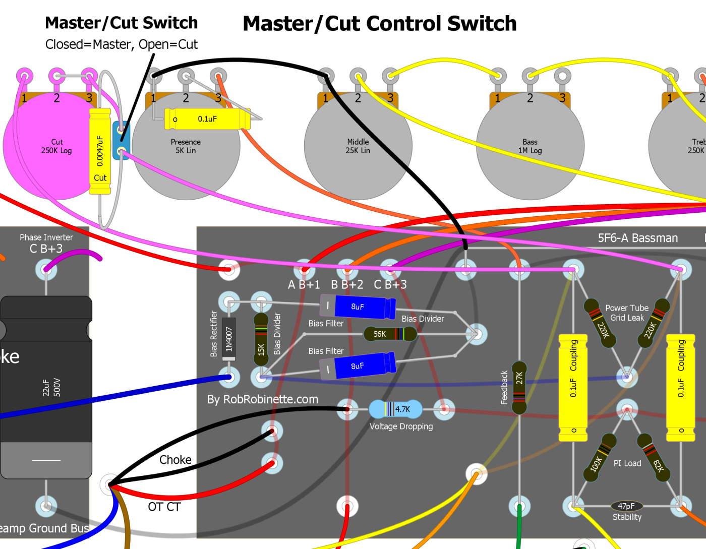
If you prefer a switch over a push-pull pot then use this layout. A Master / Cut switch is mounted next to the Cut Pot. It is a SPST On-Off mini-switch. Close the switch for a Master Volume and open the switch for a Cut Control.
Bias for Tone
Don't forget that a hot biased amp will sound different than a cool biased amp and a cold biased amp can sound thin and sterile. I always recommend sampling the clean and overdrive tone and different volume levels each time a bias adjustment is made. You may find you prefer a cooler bias than the standard 70% target for push-pull amps. Many Fender amps from the 50's and 60's came with a bias level between 50 and 60%. See my How to Bias a Tube Amplifier for more info and use my Bias Calculator page to calculate plate dissipation %.
Power Tube Plate-to-Plate Snubber Cap
This is similar to the phase inverter snubber above but goes between the power tube plates for the very latest tone tweak possible. The cap removes some very high frequencies. I suggest you try a 470pF 600v cap.
Power Tube Plate-to-Plate High Cut Control
The early Fender Model 26 Deluxe used a power tube plate-to-plate High Cut Control. Wire the cut pot as a variable resistor so that as you turn the knob up (clockwise) resistance increases. Up = more resistance = brighter tone.
Note that the pot has approximately 375v DC on it because it is connected between the power tube plates. This is not a safe design. A second cap needs to be added to the other Tone pot wire to keep DC out of the pot. A 0.1uf 600v cap would be adequate and I also recommend upping the Tone cap to 600v.
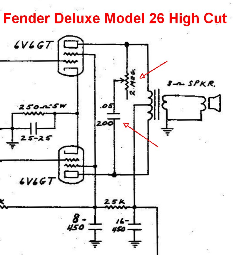
A 2 Meg audio pot and .047uF 400v cap (or higher voltage rating, 200v is too small for many amps) connect the power tube plates to remove high frequencies very late in the amplifier circuit.
Output Transformer Saturation
An undersized output transformer can be saturated (maxed out) by the guitar signal coming off the power tube plates. When this happens the loudest passages will be capped causing compression. This dynamic compression can add to the character of an amp by adding note bloom and sustain. This tends to make an amp sound more round and tubey and less sterile. A smaller output transformer can help a modern amp sound more vintage. Most high gain amps do not use undersized transformers.
A "right sized" or oversized output transformer will let you get the maximum volume out of your amp and enhance dynamics, especially the low end.
Doh! The Speaker
The amp's speaker has more affect on the amp's tone than any other component and a swap is usually an easy job. The problem is unless your amp is a known standard you never know quite what the amp will sound like with a new speaker until you try it. Most amps allow you to plug your amp into an external cab so take advantage of this feature and try your buddies' cabs and speakers.
All other things being equal, a closed back speaker cab will have a firmer and deeper low end than an open back cab. Marshall amps were typically paired with closed back extension cabs while the classic Fender tone usually comes from open back cabs and combos.
The speaker's efficiency rating given in dB can have a dramatic affect on an amp's loudness. Many 1950's guitar tube amps sound most authentic when paired with a speaker with relatively low efficiency around 95dB. If you want more breakup at lower volume a low efficiency speaker will let you turn your amp up more for the same output volume. Conversely, if you're fighting a ham-fisted drummer and need more clean headroom a high efficiency speaker of 100dB or higher can help you be heard.
Ted Weber of Weber Speakers on the Difference Between AlNiCo (aluminum, nickel and cobalt) and Ceramic Speakers
The whole 'AlNiCo mojo' is about smooth compression at high average levels, such as what you would have running the amp flat out. AlNiCo (Aluminum-Nickel-Cobalt) is an alloy magnet and all alloy magnets are easier to demagnetize than comparable Ceramic (Strontium Ferrite) magnets. What this means is that as the voice coil starts moving in response to the input signal, it generates a magnetic field of its own that tries to demagnetize the magnet. As its effect lowers the available magnetic field of the AlNiCo magnet, the speaker becomes less efficient, the voice coil moves less, etc. The physics of it is that the small magnets near the surface of the magnet poles (called 'domains') begin to change state, or flip directions. The result is smooth compression, the same kind of operating curve compression that occurs in a tube amplifier. The ceramic magnet, on the other hand, doesn't compress or demagnetize as easily, so the voice coil moves to its mechanical limit and won't go any farther. This is why some players say ceramics sound a little edgey at high average levels as opposed to AlNiCo. However, by properly designing the entire magnetic circuit, Ceramics can be made to behave quite well for desirable guitar amp tone and dynamics. You might compare the two magnetic circuits to solid state amps versus tube amps, where the solid state amp gives it all its got then clips hard, while a tube amp compresses nice and smooth. The extension of this idea, then, is that with the AlNiCo, like the tube amp, you can seem to have a louder average volume since it gets compressed smoothly. By the way, the compressing or demagnetization that occurs with the AlNiCo is not permanent. It springs right back to its design operating point. A voice coil is like an electric motor. The bigger the voice coil, the more wire used, the more torque or pulling power you have to move the cone. With the proper match of components, you can get more sensitivity, wider frequency response, and more power handling ability.
Layout With Major Components Names

By Rob Robinette
References
RCA Corporation, RCA Receiving Tube Manual, RC30.
Merlin Blencowe, Designing Tube Preamps for Guitar and Bass, 2nd Edition.
Merlin Blencowe, Designing High-Fidelity Tube Preamps
Morgan Jones, Valve Amplifiers, 4th Edition.
Richard Kuehnel, Circuit Analysis of a Legendary Tube Amplifier: The Fender Bassman 5F6-A, 3rd Edition.
Richard Kuehnel, Vacuum Tube Circuit Design: Guitar Amplifier Preamps, 2nd Edition.
Richard Kuehnel, Vacuum Tube Circuit Design: Guitar Amplifier Power Amps
Robert C. Megantz, Design and Construction of Tube Guitar Amplifiers
Neumann & Irving, Guitar Amplifier Overdrive, A Visual Tour It's fairly technical but it's the only book written specifically about guitar amplifier overdrive. It includes many graphs to help make the material easier to understand.
T.E. Rutt, Vacuum Tube Triode Nonlinearity as Part of The Electric Guitar Sound
[ How the 5E3 Deluxe Works ] [ Deluxe Models ] [ DRRI & 68 CDR Mods ] [ Amp Troubleshooting ] [ My 5E3 Build ] [ Spice Analysis ] [ The Trainwreck Pages ] [ Fender Input Jacks ] [ B9A Prototype Boards ]