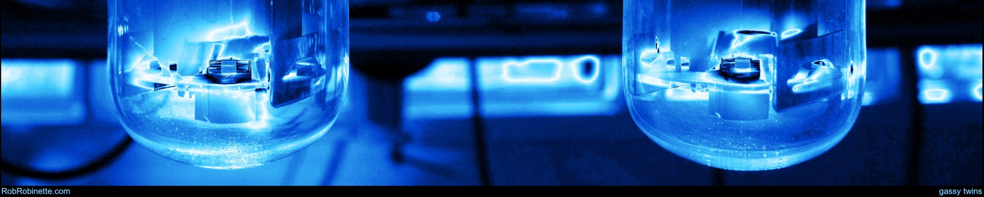
Tube Guitar Amp Troubleshooting
By Rob Robinette
Here's my technique for troubleshooting a tube guitar amplifier. Many of these techniques apply to solid state amps too.
If you are turning on a new build amp or heavily repaired/modified amp for the first time I recommend you use a light bulb current limiter and follow my Amp Startup Procedure. Following it will minimize damage due to a miswired amp.
The more you know about how tube amps work the easier they are to troubleshoot, so keep learning.
WARNING: A tube amplifier chassis contains lethal high voltage even when unplugged--sometimes over 700 volts AC and 500 volts DC. If you have not been trained to work with high voltage then have an amp technician service your amp. Never touch the amplifier chassis with one hand while probing with the other hand because a lethal shock can run between your arms through your heart. Use just one hand when working on a powered amp. You must drain the filter caps before doing any work inside an amplifier chassis. See more tube amplifier safety info here.
Preliminary Troubleshooting
Divide and conquer. Does a volume, tone or master volume control affect the noise? When a control affects the noise it usually indicates the noise is entering the amp before that control but I have seen a volume control that caused noise in a bad power tube increase so this isn't a hard-and-fast rule.
Always suspect a bad tube as they are the most common failure point in a tube amplifier. Having a spare set of tubes to swap into the amp one at a time is a must for gigging tube amp users. A bad tube can cause lots of different symptoms including everything from complete signal loss, hum, hiss, static to something that sounds like whale sounds. You name it and a bad tube can cause it. Power tubes usually wear out quicker than preamp tubes but as they say, "tubular morghulis," "all tubes must die." Don't forget to try a new rectifier tube--they can cause all kinds of problems including weird noises. Reverb driver tubes often have over 400 volts on their plates and die quicker than preamp tubes.
Loose or dirty tube socket pins can cause all kinds of hard to diagnose intermittent problems including complete loss of signal, red plating due to loss of bias voltage, weird noises, static, crackle & pop, weakening or thinning of signal output, loss of tube heat, higher than normal plate voltage, zero voltage on the cathode of a cathode biased amp--almost anything. Sometimes you can gently wiggle a tube and listen for noise. You can clean the socket by spraying contact cleaner on a tube's pins and inserting it into the socket a couple of times. See this for how to re-tension the tube pin holders.
In many Fender 1960 and newer two channel amplifiers the first tube on the right, V1, is for the Normal channel only and can be pulled out and used to replace all the other small tubes in the amp to find a bad tube. Play through the Vibrato channel and test the amp after every tube swap.
Contrary to popular belief, the power and output transformers are the least likely cause of amp problems.
Always try another guitar, guitar cable, speaker and speaker cable.
Make sure a speaker or dummy load is connected to the amp every time it is powered up.
Repairing Classic Amps
Putting fresh electrolytic capacitors in an old amp can noticeably change amp tone and playability. Old weak filter caps can loosen up the bottom end and increase voltage sag and note bloom. A 30 year old, weak 25uF cathode bypass cap that has deteriorated to 1uF will trim a lot of low frequencies. To most of us that seems like a problem that needs to be fixed but these "defects" may be the cause of the "perfect tone" this amp gives its player.
I am not saying you should leave old electrolytic caps in classic amps, my point is that a repair client may not be happy with the "new amp tone" so consider measuring and recording the location and capacitance of the old caps as you remove them so you can recreate the old tone. Time has "modified" classic amps and a cap update will undo the "mod." With old classic amps I like to discuss this with the client. Do they want the amp brought back to original specs or do they want to keep the current amp tone? This is especially true for well known guitarists. You don't want someone famous telling everyone you ruined their favorite amp.
Click on your amp's symptom:
The amp is completely dead. No lights, no sound, no speaker hiss.
The amp shows signs of life but does not put out any guitar audio. Lights are on or you can hear speaker hiss.
The amp powers up but makes weird noises likes squeals, oscillation, static or motor boating.
The amp powers up but the guitar audio sounds weak, bad or drops out completely.
The amp has excessive hum or buzz.
Troubleshooting spring reverb.
The Amp is Completely Dead
If the amp is completely silent (no speaker hum or hiss at all) then the problem can be just about anywhere in the amp but you should suspect a bad tube, blown fuse or the power supply in that order.
Try a new rectifier tube.
Try plugging in a guitar cable, turn up all the amp's volume, gain and master volume controls up a little and touch the tip of the guitar cable's other end. You should hear loud noise. If you hear noise jump to The amp shows signs of life but does not put out any guitar audio.
If the pilot light does not light you can remove the bulb and test it for continuity across the bulb terminals using a multimeter's continuity or "beep" function. A blown bulb will not show continuity.
If none of the tubes show any heater glow (dimming the room lights can help you see the tube glow) the problem is probably with a blown fuse or the power supply.
Most older amps have a mains fuse holder on the control panel or on the back of the amp chassis (usually with a push-and-turn cap). Most Fender guitar amp fuses are MDL "slow blow" or "time delay" 1/4 inch (6mm) wide by 1 1/4 inch (30mm) long.
Replace the fuse with one with the exact amp rating listed on the back of the amp, typically 1 or 2 amps. The voltage rating of the fuse can be anything at or above your wall voltage (125v USA or 240v Europe). A 250V AC rated fuse will work fine worldwide.
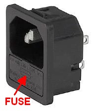
Many newer amps have the mains fuse built into the IEC power cord socket. You have to pry open a little cover to get to the fuse. Check the fuse for continuity with your multimeter. They can look good but still be blown.
IEC Power Cord Socket
Many amps have internal fuses mounted on the circuit board or on wires in in-line fuse holders. Any one of these fuses can make the amp silent. Again, test all the fuses for continuity with your multimeter. You should remove a fuse to test it because if left in-circuit you can get a false "good" reading.
If after replacing the fuse the amp blows the new fuse see the If the Amp Blows Fuses section.
If the Amp Blows Fuses
If the amp is blowing fuses at power up replace the fuse and plug the amp into a light bulb current limiter and power it up. A light bulb limiter allows you to power up a new or problem amp and limit damage to the amp from miswiring or other defects. If an amp is blowing fuses the limiter will allow you to power up the amp, not blow a fuse and troubleshoot. The limiter keeps the current flowing through the amp low enough to not blow the fuse. The bulb should initially go bright as the power transformer and filter caps charge, then the bulb should dim noticeably if the amp is healthy. If the bulb burns at its full brightness then a problem is allowing too much current to flow through the amp.
If you don't use a light bulb limiter then substitute "blows a fuse" for "light bulb goes full bright" below.
Simple Light bulb Current Limiter
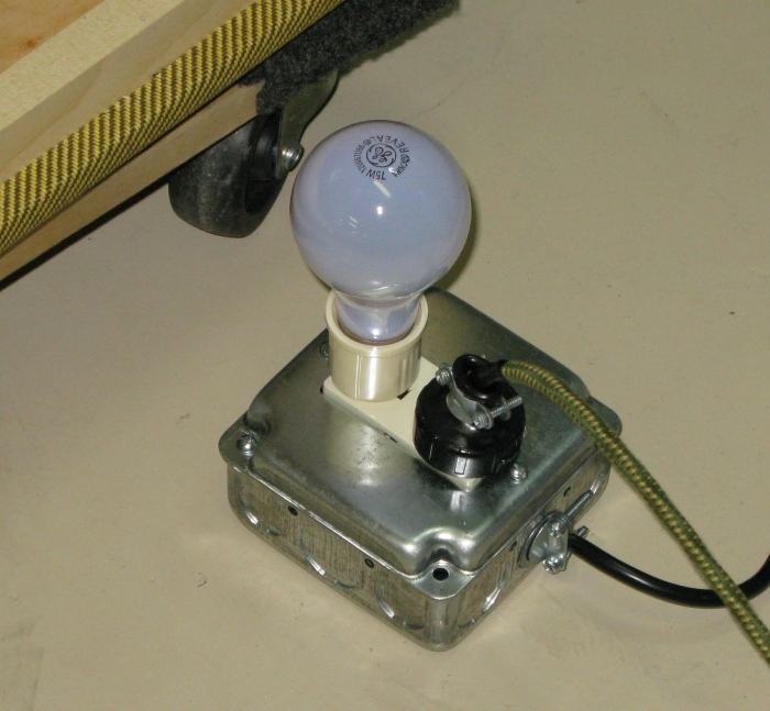
Note: The amp will sound funky and voltages will be lower than normal when powered by the limiter. If you can't find a 100 watt bulb for your limiter a 150 is the next best thing. You can not use an LED or fluorescent bulb.
1. Plug the amp in to the light bulb limiter and turn the amp on in 'standby' mode if available. If you don't have a standby switch jump to Power Transformer.
If the bulb glows dim, which is normal, jump to Step 2.
If the limiter's bulb burns at full brightness in standby then a problem is in the power cord, power transformer, heater wiring, fixed bias circuit (fixed bias amps only) or rectifier. These are the only things usually powered in standby.
If your amp has a rectifier tube then remove it and power up the amp.
If the bulb goes dim then the rectifier tube or socket is the problem. Try another rectifier tube and inspect the rectifier tube socket.
If the bulb glows bright check the rectifier tube socket and its wiring. If you don't find a problem move to the Power Transformer.
Remove all the tubes and power up the amp with the power and standby switches on (fully powered). If the bulb glows dim (which is normal) then jump to Step 2.
Warning: With no tubes installed many amps will leave their filter capacitors fully charged. You must measure for DC voltage at the filter caps and drain the caps if voltage is over 30v before doing any work inside the chassis.
If the bulb glows bright there is a short so trace the voltage from the power transformer and look for a short--and don't forget the bias circuit.
If you don't find the problem, drain the caps and disconnect all the power transformer secondary wires and tape them off individually so they can't short to the chassis or make contact with one another.
Power up the amp, if the light bulb doesn't glow at all or glows dim then jump to the next paragraph. If the bulb glows bright then the power cord or transformer winding is shorting out internally. Drain the caps and disconnect all three power cord wires, wrap each one in electrical tape and plug in the amp. If the bulb doesn't light then the transformer is shorted internally and must be replaced. If the bulb glows bright the power cord is shorting so try a new power cord.
If the light bulb doesn't glow with all the secondary wires disconnected then there is a short in the wiring after the transformer secondary leads downstream in the rectifier, 6.3v heater wiring, 5v heater wiring or bias circuit.
Power down the amp and drain the caps. One at a time connect the power transformer secondary wire pairs. Start with the high voltage wires to the rectifier. Power up, if the light bulb doesn't glow then its downstream wiring is OK. If the bulb goes bright you know there is a problem downstream of the connection in either the rectifier tube socket wiring or in amps with a solid state rectifier the problem can be in the rectifier, filter caps, output transformer or tube socket connections. If your bias circuit is powered by the high voltage taps then it is a suspect too. Unsolder the connection from the last filter cap that supplies the preamp. If the bulb doesn't light the preamp wiring is OK, disconnect the power tube screen connection and test. If it's ok then you probably have a shorting capacitor. Unsolder them and test.
If the high voltage connection tested good power down, drain the caps and connect the 6.3v heater wires. Power up and if the bulb doesn't light the heater wiring is OK. If the bulb burns bright then there is a wiring problem in the heater wires, heater artificial center tap or tube sockets. Using a magnifying glass carefully inspect every heater wire connection. If you don't find a problem and your amp has an artificial center tap then replace both resistors.
If the 6.3v circuit tested good power down, drain the caps and connect the 5v heater wires that power the tube rectifier. If your amp has a solid state rectifier skip this step and move to the fixed bias circuit. Power up, if the bulb doesn't light then move on to the bias circuit. If the bulb goes bright carefully inspect the rectifier tube wiring--there's a short somewhere.
If the 5v circuit tests good and your amp has a power transformer fixed bias tap, power down, drain the caps and connect the fixed bias. If the bulb doesn't light the circuit is OK. If it goes bright there is a problem in the bias circuit. Carefully inspect the circuit looking for shorts to ground. If your fixed bias circuit runs wires under the circuit board then that wire may be shorting to the chassis. Test the bias circuit components.
You can also test a power transformer by measuring the resistance between leads. A healthy Hammond 270AX 240-0-240v power transformer measured: 14 ohms between primary leads, 223 ohms between the secondary center tap and HT wire 1 and 250 ohms from center tap to HT wire 2, 0.3 ohms between the 6.3v leads (this is low enough resistance to beep during a continuity test). Your power transformer should measure somewhere near these values and not show an open (mega ohms) or shorted (0 ohms) connection.
2. Power down the amp and insert the tubes one by one, starting with the rectifier, then preamp tubes, then power tubes. After inserting each tube, power up the amp and check the light bulb.
If the bulb goes dim (normal) pull that tube and insert the next tube (don't remove the rectifier tube, it is needed to power the other tubes). Repeat until the bulb goes bright.
If the bulb goes bright then power down, it means you have found the problem area.
Replace that tube with a known good tube. If the bulb stays dim with the new tube you had a bad tube and should be good to go.
If the bulb goes bright with the known good tube then there is a short in the circuit near that tube. Closely inspect the tube socket with a magnifying glass for anything that would short two pins or short a pin to ground. Use your meter to check for continuity from socket pin to ground. Read the ohm rating color stripes of all the resistors in the circuit to verify their value. Closely inspect the components that are connected to that tube socket on the circuit board and check them for continuity to ground.
No Guitar Audio
The goal of early testing is "divide and conquer." We'll try to find what general area of the amp is causing the problem to narrow our search.
With the amp's power and standby switch on (fully powered) and all volumes turned full up can you hear any hiss or hum coming from the speaker? If you can then you know the mains fuse, power transformer, power tubes and output transformer are powered and at least partially working. The problem is probably between the input jack and phase inverter (or driver for single ended amps).
Some amps have multiple volume, gain and master volumes so make sure they are all turned up for testing.
If the amp powers up but is quiet or sounds bad you should always suspect a bad tube. You should have a spare set of known good tubes on hand so swap out all the tubes one at a time and see if that fixes your problem.
Try another guitar and guitar cable.
Try all the input jacks. If one channel works and the other doesn't you know the problem is in the bad channel between the input jack and where the two channels join.
Dirty or bent FX loop jacks. Insert a jumper or guitar cable from FX Out to FX In to see if that cures the problem. If the jumper cable does fix your problem then try cleaning all the jack contacts, especially the switch contacts. If that doesn't fix it replace the bad jack.
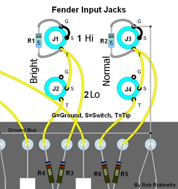
For a new amp startup a very common "no guitar sound" problem is incorrect input jack wiring. To test your input jack wiring, with the amp off, insert a guitar cable into the input jack, then measure the other end of the cable from tip to sleeve for resistance. The Hi jack should measure about 1 megaohm which is the standard value for the input resistor which is connected across the input jack's tip and ground terminals. The Low jack should measure around 136k.
Fender Style Hi-Low Input Jack Tests
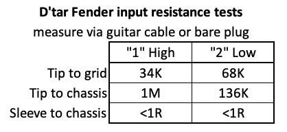
If you measure near 0 ohms between the tip and sleeve the tip of the guitar cable is making contact with ground and sending all the guitar signal to ground. Inspect the input jacks carefully and make sure the switch (shunt) terminal is really the middle terminal as shown on amp layouts. On some Switchcraft clone jacks the switch terminal is not the middle terminal. Make sure the jacks' switch disconnects when a guitar cable plug is inserted.
A bent input jack switch (shunt) terminal can short audio to ground. Visually confirm that the tip and switch terminals separate when a plug is inserted. You can usually bend the terminals so that they close with no plug and open with a plug inserted.
If the amp has an effects loop try plugging the guitar into the FX loop Return jack. That will bypass the gain stages and circuitry upstream. If that works you know the problem is upstream of the Return jack.
Check the speaker and speaker cable. A speaker cable with a break in it can fry the output transformer. Make sure the speaker is plugged into the correct speaker jack. Many Fender amps ground out the signal if you plug only one speaker into the Aux speaker jack. Try all the speaker jacks.
Play another amp through the speaker to verify its tone and function. You can also connect another speaker to the problem amp, if the amp sounds good you know you have a bad speaker.
Inspect the speaker connections at both ends of the speaker cable. Slide-on spade connectors can make intermittent connection and cause buzz, static and audio drop out. I do not like spade connectors--solder that speaker cable to the speaker terminals because you can blow the output transformer and/or power tubes if that connection breaks.
If the "no guitar audio" problem persists continue to: Going Inside the Chassis.
Weird Noises
Finding the Noise
Start by pulling the first preamp tube, powering up and seeing if the noise is still present. If it is then you know the noise is being generated downstream of the tube you pulled. Power down, pull the next tube and continue until the noise goes away, then you know the noise is coming from between the last tube you pulled and the previous tube.
You can sometimes identify the problem by waiting for it to occur then carefully spray freeze spray to cool amp components and solder joints. If spraying a part or solder joint causes the issue to go away or come back you've located the problem.
Weird noises, including squealing, wooshing, clicking, static, honking, motor boating, etc. can be caused by:
A bad tube so swap out the tubes one at a time for known, good tubes.
A microphonic tube or other component can cause rattles, buzzes, rings and other strange noises in combo cab amps. If you connect your amp to an extension cab and disconnect the internal speaker and the noise goes away it's probably caused by a microphonic component or possibly a cab rattle. You can gently tap the tubes with a chopstick or wooden pencil with the amp on and listen for excessive noise. You can also put light pressure on each tube using a chopstick or gloved hand and then play the offending note to try to identify the noisy tube. High temperature o-rings placed on preamp tubes can help in combo cabs but metal tube shrouds won't fit over them.
What a Microphonic Tube Sounds Like
Dirty or loose tube sockets can cause everything from no signal at all to intermittent static, pops, whooshing and hum. If wiggling the tubes causes noise then put some contact cleaner on the tube's pins and insert them into the socket two or three times. You can also re-tension loose sockets for solid pin contact.
Inspect the speaker connections--both ends of the speaker cable. Slide-on spade connectors can make intermittent connection and cause buzz, static and audio drop out. I do not like spade connectors--solder that speaker cable to the speaker terminals because you can blow the output transformer and/or power tubes if that connection breaks.
In combo amps the cab, speaker or speaker baffle can vibrate, rattle and buzz. Try sitting on the cab while playing or have someone put pressure on the baffle board to identify the problem area. Try a separate extension cab to verify it's a cab issue. You can glue and screw small braces to tighten up loose joints. To help troubleshoot you can use a signal generator (or phone ap) connected to the amp and play with the signal frequency to find the resonant tone that causes the rattle or buzz. Once you get a continuous buzz it will be easy to find the rattle using your hands to dampen different parts of the cab. You can also use a chopstick to put pressure on amp components to look for a microphonic component like a tube or capacitor.
Electric sounding arcing or zap noises can be caused by tube arcing or loose grounds. You can sometimes locate an actual arc by opening the chassis and playing the amp in the dark. Look for little flashes of light when the "zap" sound occurs. Look for loose, broken or unsoldered joints, especially on the ground bus and where the bus ties to the chassis.
Dirty FX loop jacks. Insert a jumper or guitar cable from FX Out to FX In to see if that cures the problem. If it does fix your problem try cleaning all the jack contacts, especially the switch contacts. If that doesn't fix it replace the jacks.
Dirty or worn pots. Dirty pots can cause intermittent contact, signal dropout and static. Most pots have a hole in their shells so you can squirt contact cleaner into them. Run the back and forth through their full travel very quickly several times right after you squirt them.
Positive Feedback from the negative feedback circuit. When you start up a new build amp with an NFB loop or replace an output transformer you have a 50% chance of getting a loud squeal from positive feedback (usually not affected by the volume control). Swap the output transformer's primary wires to make the feedback negative. The primary wires run from the output transformer to the power tubes. You can usually swap the secondary wires (speaker jack wires) instead but you can not swap them if you have a multi-tap secondary (4-8-16 ohms for example). Positive feedback doesn't always cause a loud squeal. In my 5F6A Bassman it just caused strange noise layered on top of all the notes.
Lead dress causing capacitive coupling which can cause hum, noise, squeals and oscillation. Chopstick the amp. You can use a non-conducting wooden chopstick to move wires around with the amp operating and volume full up to find the source of noise. It can also be used to apply pressure to components and solder joints to identify weak or broken components and joints.
Silent oscillation (above human hearing) can cause lower than normal amp voltages, lower than normal (or no) output volume and temporary signal dropout. Use chopsticking to find lead dress issues that can cause oscillation. Snubber caps can be used to filter above human hearing frequencies. Temporarily alligator clipping a 1nF (1000pF) or 500pF snubber cap across the preamp tube plate load resistors, one at a time, can help find the problem.
Weak or failing filter caps can cause hum, oscillation, squeal and motorboating, especially in high gain amps. You can temporarily alligator clip a new cap in parallel with an existing cap. If the hum or oscillation goes away then replace the old cap.
Defective plate or cathode resistors can cause constant static, crackle and pop noise. Sometimes putting some pressure on the resistor with a chopstick or spraying it with freeze spray will change the noise and help you identify the bad resistor. I like to use 2 watt resistors for all preamp plate resistors to lengthen their lifespan and reduce amp hiss.
Popping or squealing when a guitar cable is plugged in. A bad 1M input resistor (usually mounted on an input jack) will allow the first gain stage grid to float in the short time between the jack shorting switch opening and the cable plug making full contact. You can test this by opening the input jack switch, if it squeals the input resistor is bad. Measure the resistance across the resistor and if it measures good re-flow its solder joints and check the input jack ground.
Intermittent noise, crackling static or noise that begins or goes away when the amp warms up is sometimes caused by a weak component or bad solder joint that is affected by heat. You can sometimes identify the issue by waiting for the problem to occur then carefully spray freeze spray to cool amp components and solder joints. If spraying a part or solder joint causes the issue to go away or come back you've located the problem.
Motorboating (amp sounds like a boat engine) is usually caused by a weak or damaged power supply filter cap. You can temporarily alligator-clip an extra filter cap in parallel with the caps, starting with the first filter cap. If the temporary cap fixes the problem then replace the original cap. Also verify the power supply voltage dropping resistor values.
Ghost Notes are caused by a noise mixing with a note to create a harmonic note that shouldn't be there. Hum, oscillation and other noise can cause them.
Conductive circuit boards in classic amps can cause a multitude of problems. Many classic Fender amps from the '50s to the '70s were made of a material that will hold moisture and conduct electricity from one eyelet to another. This can cause all sorts of problems and noise. Some old circuit boards were coated with wax to fight moisture but after 60 years the wax isn't holding up. You can sometimes measure voltage from a high voltage eyelet to the circuit board immediately around the eyelet to check for conduction. You can use a hair dryer to dry the circuit board for a temporary fix and troubleshooting. Replacing the circuit board is the best long term fix.
For more info see Going Inside the Chassis
Bad Guitar Audio
Nasty sounding guitar audio can be caused by many things including:
Strange noises and complete guitar audio dropout can be caused by oscillation. It can be caused by a dying tube but the typical culprit is an interaction between two wires. Ultrasonic oscillation (above human hearing) can block out guitar audio and silence the amp. Chopstick the amp wires, especially the tube socket wires and separate the grid and plate wires. Do this while the amp is in oscillation to see if you can get it to stop--if it's ultrasonic oscillation then feed a signal into the amp so you'll know when the oscillation stops. Use a "filter cap on a stick" (500pF cap with a ground clip on one end) to filter all the tube grids to see if you can kill the oscillation. When you find the guilty tube you can add a filter to the grid or bypass its plate load resistor with a cap. Use the smallest cap that solves the problem for the least side effect.
A bad tube so swap out the tubes one at a time for known, good tubes.
Dirty FX loop jacks. Insert a jumper or guitar cable from FX out to FX in to see if that cures the problem. If it does fix your problem try cleaning all the jack contacts, especially the switch contacts. If that doesn't fix it replace the jacks.
Dirty or worn pots. Dirty pots can cause intermittent contact, signal dropout and static. Most pots have a hole in their shell so you can squirt contact cleaner into them. Run the pot back and forth through its full travel very quickly several times right after you squirt them.
A bad solder joint. Applying pressure with a chopstick and hearing noise can identify a bad joint. Freeze spray can also help identify bad solder joints by cooling them and causing a change in noise.
Ghost Notes are caused by a noise mixing with a note to create a harmonic note that shouldn't be there. Hum, oscillation and other noise can cause them.
Cone Rub. The speaker voice coil rubs its surround. Typically happens during loud, low notes. Try another speaker to identify a bad speaker. Sometimes mounting the speaker upside down will stop the cone from rubbing. You may have to have the speaker re-coned to get rid of cone rub.
Inspect the speaker connections--both ends of the speaker cable. Slide-on spade connectors can make intermittent connection and cause buzz, static and audio drop out. I do not like spade connectors--solder that speaker cable to the speaker terminals because you can blow the output transformer and/or power tubes if that connection breaks.
For a new or recently repaired amp using the incorrect value of a component can cause low output or funky audio. Verify the value of all resistors and caps.
A disconnected component. Component leads can break and wires can pull loose. Resistors can crack yet look perfectly normal. Chopsticking components and wires can help identify the loose connection or bad component.
Conductive circuit boards in classic amps can cause a multitude of problems. Many classic Fender amps from the '50s to the '70s were made of a material that will hold moisture and conduct electricity from one eyelet to another. This can cause all sorts of problems and noise. Some old circuit boards were coated with wax to fight moisture but after 60 years the wax isn't holding up. You can sometimes measure voltage from a high voltage eyelet to the circuit board immediately around the eyelet to check for conduction. You can use a hair dryer to dry the circuit board for a temporary fix and troubleshooting. Replacing the circuit board is the best long term fix.
A bad component:
Blown power tube screen resistor. This is a common cause of a weak sounding amp. When a power tube blows it can short the plate and screen and cause the screen resistor to burn and blow. A blown or cracked resistor can look normal--gentle pressure from a chopstick can help find a bad resistor. Measure the resistance across the resistor.
Leaking coupling capacitor. A leaking cap can cause scratchy pots and affect preamp and power tube bias. Measure the DC voltage on tube grids and look for anomalies.
Shorted resistor. Measure the resistance across the resistor. A shorted resistor will show very low or even 0 ohms.
Open resistor. Applying light pressure to the resistor and hearing noise can sometimes identify a bad resistor. Measure the resistance across the resistor. An open resistor will show a very high resistance well beyond the resistor's rating.
If the output transformer shorts between windings it can lead to no output, weak output or funky sounding output. You can test the transformer by measuring the resistance between its leads. Drain the filter caps and remove the rectifier and power tubes before making the following resistance measurements:
For push-pull transformers you should see approximately the same resistance between each secondary wire at each power tube and the center tap--typically somewhere between 10 to 200 ohms.
A shorted primary winding will have much lower resistance compared to the other winding and typically measure at less than 10 ohms.
The secondary windings will often measure less than 1 ohm between all the secondary leads so it is difficult to detect a shorted secondary.
If a transformer winding is open (break) it will show a very high resistance between the primary leads or between the secondary (speaker) leads (typically 500k or higher).
A short between the primary and secondary windings will typically show less than 10 ohms resistance between the primary and secondary leads.
Measure the resistance between all the leads and chassis ground--low resistance of less than 10 ohms indicates a short to the transformer's iron core.
For comparison my healthy Hammond 125C push-pull output transformer measured: red center tap to brown 150 ohms, red center tap to blue 116 ohms, brown to blue 268 ohms. All secondaries measured .2 to .6 ohms between them. A Hammond 125GSE single-ended output transformer measured 53 ohms between the two primary wires. All of the secondaries measured .2 to .3 ohms. Both transformers measured an open circuit (no connection) between their primary and secondary wires and between all wires to the transformer outer metal shell.
If any of the above faults are present your best bet is to just replace the output transformer. For valuable vintage transformers it is possible to have them rewound.
For more info see Going Inside the Chassis.
Hum and Buzz
"Teach it the words and it will stop humming."
Start with the basics. Does any volume or master control affect the hum or buzz? If yes then the noise is getting into the circuit before the control.
Is the noise in both channels? If yes then the noise is entering the circuit after the channels merge. If no, the noise is entering upstream of the channel merge.
If the amp has an FX return jack plug your guitar in there and see if the noise is still present (turn the guitar volume control down before plugging in then turn it up for the test). If no noise you know the noise is coming from upstream of the FX return jack.
Loud hum from a newly built amp is almost always caused by a bad or missing ground. Check for continuity between everything that should be grounded and the chassis. A joint with no solder can cause intermittent loud hum. Inspect every solder joint with a magnifying glass. It's very common to leave a joint or two without solder.
Hum and noise can be caused by the chassis being out of the chassis and open to environmental electromagnetic noise.
Be sure and try another guitar and guitar cable. Also try the amp in another location because noise is often caused by dirty power (perhaps caused by a refrigerator's compressor motor) or radio frequency interference (RFI) caused by a cell phone, noisy light dimmer, fluorescent lights or other electrical equipment. Before taking the cover off your amp try it in another location, preferably in another building.
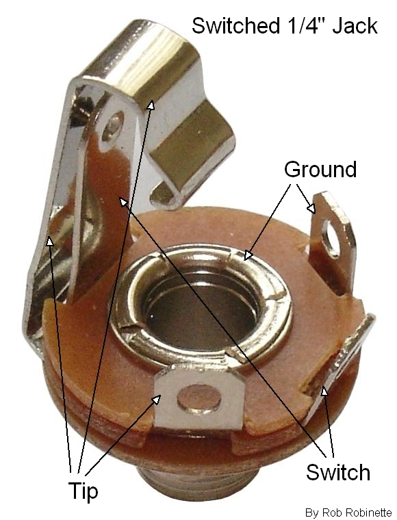
An input jack whose switch tab isn't making contact when no guitar is plugged in can cause loud hum or buzz (see jack picture above). Try pushing the switch tab closed and see if it kills the noise. This is especially true if plugging in a guitar decreases amp noise.
In combo amps the cab, speaker or speaker baffle can vibrate, rattle and buzz. Try sitting on the cab or putting pressure on different parts of the cab, speaker baffle and speaker frame (it helps to have a friend play while you prod).
A dying tube can cause 50 or 60Hz hum from heater-cathode leakage but can also cause 100 or 120Hz hum so swapping out every tube should be done before going any further. I have had brand new preamp tubes hum loudly so try swapping them all.
After trying different tubes the next step is to identify the type and frequency of the hum or buzz. Buzz has a sharp tone to it where hum has a smooth sound. A "buzz" is caused by noise that can be seen on an oscilloscope as a waveform with sharp spikes.
In the United States hum and buzz usually comes in two frequencies, 60 and 120Hz (Hz means cycles per second). If your power runs at 50Hz like in Europe you will have 50 and 100Hz hum and buzz. Determining the frequency of the noise will help you track down the source. See this Youtube video at 2:15 for samples of both types of hum. 50 and 60Hz hum usually comes from the power transformer circuit, fixed bias circuit or heater wires. 100 and 120Hz hum comes from the power supply after the rectifier.
Dirty, corroded or loose tube socket pins can cause hum and buzz. You can clean them by spraying contact cleaner on a tube's pins and insert it into the socket a couple of times.
Microphonic tubes can rattle, buzz and ring. Touching the tubes gently with your chopstick or a gloved hand while playing something that makes it buzz can help you identify the bad tube.
A hot power tube bias can cause loud hum.
A large bias imbalance between power tubes can cause 60Hz heater hum.
Inspect the speaker connections--both ends of the speaker cable. Slide-on spade connectors can make intermittent connection and cause buzz, static and audio drop out. I do not like spade connectors--solder that speaker cable to the speaker terminals because you can blow the output transformer and/or power tubes if that connection breaks.
Adding aluminum or copper foil tape to an amp cab to cover the chassis opening can help reduce RFI. The tape will need to make good contact with the chassis for it to act as an RFI shield. For the 5E3 Deluxe and other tweed amps the tape would be applied to the inside of the wooden back panel to cover the chassis opening. For more modern Fender amps you would apply the tape to the underside of the top of the cab.
Connecting the power transformer high voltage center tap directly to the first filter cap negative terminal can reduce hum and buzz by minimizing pulsing 120Hz ground return current.
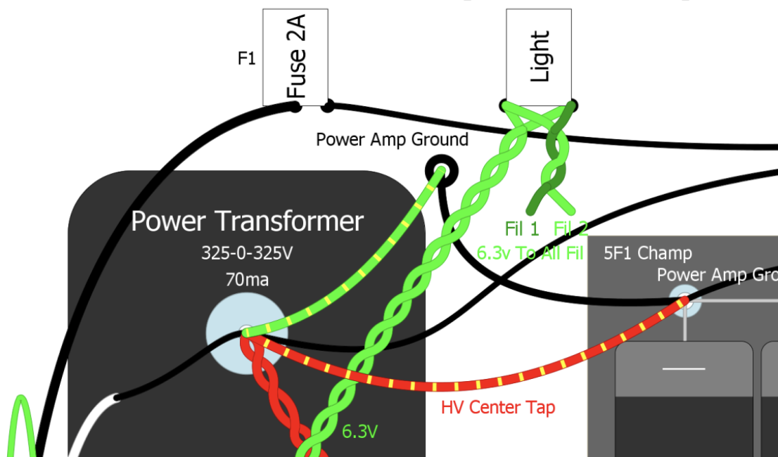
Connecting the (red/yellow) high voltage center tap on the first filter cap negative terminal can reduce 120Hz hum and buzz.
If your amp has an unused triode you should connect the unused plate, cathode and grid to ground.
"Chopsticking" the Amp
You can use a non-conducting wooden chopstick to move wires around with the amp on and the volume up to find the source of noise and identify lead dress problems. On my first amp build I had the V1A plate and grid wires lying on top of one another which created a moderate hum. Simply moving those wires apart made the amp almost silent. A chopstick can also be used to apply gentle pressure to components and solder joints to identify weak or broken components and joints.
Sometimes you'll have to resort to using an oscilloscope and signal generator to track down the source of a difficult to identify hum or buzz. See the oscilloscope section for more info.
50 or 60Hz Buzz
50 or 60Hz buzz is sometimes caused by power line noise and can be addressed by applying a small, high voltage filter cap across the high voltage rectifier input wires. This .02uF 3KV (3000v) ceramic disc cap works well for this. I usually solder one across the rectifier tube socket where the two high voltage power transformer wires connect. For a solid state rectifier solder the cap across the high rectifier inputs.
Buzz can also be caused by AC components. I had a nasty 60Hz buzz that was caused by the placement of a 120v pilot light too close to the amp's signal wires.
Radio Frequency Interference or RFI can sometimes be heard as a 50 or 60Hz buzz. Adding copper or aluminum foil tape to the back of a chassis cover can help reduce RFI. Moving sources of RFI like cell phones, light dimmers and fluorescent lights away from the amp can also help.
100 or 120Hz Buzz
100 or 120Hz buzz can be caused by a bad tube so swap in a new set of tubes. Buzz can also be caused by a noisy rectifier. This can usually be eliminated by placing .02uF 1KV caps in parallel with each rectifier diode. If the rectifier is inside a housing then running caps from the two rectifier inputs to the + and - terminals usually works well.
50 or 60Hz Hum
50 or 60Hz hum usually comes from the power transformer or its wiring, the fixed bias circuit, the tube heater wires or from external RFI caused by fluorescent lights, dimmers and other sources.
Assuming you've tried the amp in a different location, 50 or 60Hz hum must be generated by the power transformer circuit or the fixed bias circuit (if your amp has one). Keep as much distance from the power transformer's wires and the amp's wires and circuitry as possible. Heater wires should be twisted and the untwisted wire that goes to each tube pin should be as short as possible with no big loops. Signal wires should cross the heater wires at 90 degrees to minimize coupling.
You can temporarily power your 6.3v heaters with a 6 volt lantern battery (available at Walmart). If the objectionable hum goes away under battery power you know your hum is coming from the 6.3v heater circuit.
Higher than standard heater voltage can increase hum. If your heater voltage is higher than approximately 6.6v it would be a good idea to reduce the heater voltage to 6.1 to 6.5 volts. See this link for information on how to reduce heater voltage.
If your amp's power transformer has no 6.3v heater center tap then the amp needs an artificial center tap. Verify there is an artificial center tap installed and check the resistance of its two resistors. A missing 6.3v center tap or a burned out resistor will usually cause loud hum.
To troubleshoot the fixed bias circuit verify its ground connections are good and you can check the caps by temporarily alligator clipping another cap in parallel with the circuit's caps. If adding the cap reduces hum then replace the cap.
You can usually get the lowest amount of 60Hz heater hum by replacing a real 6.3v center tap or artificial center tap with a Humdinger pot. A Humdinger pot allows you to adjust the resistance between the two 6.3v heater lines to ground to achieve minimum hum. You adjust it by ear with the amp turned up to max to hear the hum best. You can also connect a Humdinger's ground connection (wiper) to a cathode biased amp's cathode resistor to elevate the heater ground reference for even more hum removal. See this link for more information on installing a Humdinger pot.
Push-pull amps should have their power tubes wired in phase so the tubes can use common mode noise rejection. For in phase wiring each heater wire should connect to the same heater pin on the two power tubes. This is why it's a good idea to use two colors of heater wiring so you can keep the phase correct.
Parallel power tubes should be wired out of phase to help cancel hum between the power tubes.
100 or 120Hz Hum
This is probably the most common hum in an amp. It can be caused by:
A bad tube so swap out the tubes for known, good tubes.
An input jack that doesn't ground out when nothing is plugged in. If the jack's shunt switch does not make good contact with the jack's tip connector you will get loud hum when no guitar is plugged in but the amp will sound fine when you plug in a guitar.
Worn out filter capacitors. Electrolytic filter caps have a typical lifespan of 15 to 20 years. You can test for bad filter caps by alligator clipping in a parallel cap. If the new cap reduces hum then replace the original cap. If your amp is fixed bias don't forget the fixed bias circuit filter cap(s).
Missing ground. Loud hum can be caused by components that should be grounded but aren't. Forgetting to solder a volume pot's ground wire or a cold solder joint on a cathode resistor's ground are two common causes of loud hum. I like to use an alligator clip wire and connect one end to the chassis and carefully probe all the amp's ground connections to see if I hear an improvement. Touch the ground probe to all volume pots' ground terminal, the ground side of preamp cathode resistors, etc. Pressing solder joints with a chopstick can also help find bad ground solder joints.
Loops in the ground circuit. If your input jacks are grounded to the chassis and you also run a ground wire between them then a ground loop is formed (chassis is one side, the wire is the other) which can act as an antenna and pick up RFI noise and hum. You will also form a ground loop if you use shielded cable inside the amp and ground both ends. You should only ground one end of shielded cable.
Lead dress (wires too close to one another causing capacitive coupling) Chopstick the amp's wires around with the amp on and the volume up to see if you can decrease the hum. Pay close attention to the tube grid and plate wires--keep them as far apart from one another as possible. My first amp build had a loud hum because the first preamp stage's grid and plate wires were sitting on top of one another. Separating the wires silenced the amp.
Chasing Down a Nasty Buzz
After I finished testing and tweaking the Deluxe Micro prototype in bare circuit boards I mounted them in a Hammond blank chassis. When I fired up the newly mounted amp I had a nasty buzz at max volume that wasn't there before I put it in the chassis. It didn't sound like smooth 60Hz heater wire hum or 120Hz power supply ripple hum so the investigation began.
The amp with no guitar cable plugged in was absolutely silent at max volume. The buzz could be controlled by both the volume and master volume controls. The amp's tone control could almost entirely eliminate it when turned full down. The guitar's tone control could completely eliminate the noise when turned full down. Hmmm. The buzz didn't change with guitar movement or when touching the guitar's strings or grounded metal bridge.
Since the volume and tone controls affected the noise I knew it was entering the amp before the control--somewhere between the guitar and the volume pot.
My first instinct was I had a bad cable or a guitar issue. I tried another cable--no change. I tried my Strat--no change. I tried a cable with no guitar connected and got the expected crescendo of noise.
My next suspect was the fluorescent lights that light the basement workshop. I turned them off and the amp looked cool in the dark as it spewed forth The Buzz.
Maybe it was power line noise. I diligently moved the amp to another part of the house and tried again--no change.
Time to get into the chassis. My first thought was a bad ground connection so I alligator clipped a wire to the chassis and carefully probed all the ground connections in the amp to see if I heard an improvement but found no success.
My next step was lead dress. I used a wooden chopstick to push around wires while listening for an improvement in noise. I did find that the input jack wires that ran by the power switch and across both circuit boards were picking up some 60Hz hum from the power switch. I replaced the input jack and headphone jack wires with RG174 coax which eliminated the hum but had no effect on The Buzz.
Time for the oscilloscope. I injected a 500Hz .1v signal into the amp's input jack. I connected the oscilloscope's ground probe to the preamp ground and connected the probe to the input jack tip. I zoomed in on the 500Hz signal and played with the tone control to change the volume of The Buzz but couldn't see any signal artifact change with the guitar tone change. I jumped to the speaker output jack and tried again with no success. Next I tapped into V1A's output just after the coupling cap (to avoid high voltage DC on the probe) and repeated the tone change and again I couldn't see any change on the oscilloscope. I moved the scope probe to V1B's output and repeated the guitar tone knob dance--and there it was. A vertical spike that grew and shrank with the tone control's movement. I zoomed in the scope's display and confirmed it was THE BUZZ.
I used the scope's horizontal scan knob to move the waveform left and right so I could measure the time between spikes--16.5 milliseconds. I took the reciprocal of 16.5ms (1/.0000165) to get the frequency and the answer was--60Hz, it was wall power related after all, or so I thought. I pulled out my trusty H&K Tubemiester 5 and plugged it into the same wall power socket and fired it up--no buzz. I figured the H&K might have some power line filtering built in so that test proved nothing.
I have seen some amps with a .01uF 3KV (3000V) disk capacitor across the rectifier tube socket's high voltage input pins to pre-filter high freq noise so I gave that a try. It did help a little but THE BUZZ still lived.
I sat there staring into the amp's chassis wondering what it could be. I noticed the 120V pilot light (not a standard 6.3V light) sitting next to the input jack. This was my first build using a 120V light so I had no experience with them. I hauled the amp back to the solder station and de-soldered the light's neutral wire and fired up the amp--success! THE BUZZ was no more. It was that damn noisy bitch of a pilot light.
The fact that the amp was silent when no guitar cord was plugged in was a big clue here that I missed. With no cord plugged in the circuit from the input jack to V1A's grid is grounded so THE BUZZ was being shunted to ground. I should have focused the investigation on the input circuit from the start. 20/20 hindsight and all that. . .
When I stuffed the prototype B9A boards into the chassis I put them to the far left to make room to mount the power transformer on the far right. After getting the boards mounted I realized I had no front panel real estate on the left side of the chassis away from the inputs and preamp stages. I ended up having to mount the power switch, pilot light, guitar input and headphone jack right next to each other--which is not good--it's a cardinal sin of amp building actually and I had to pay a penance to atone for my sin.
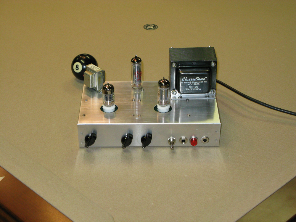
Notice the power switch, input jack, 120v pilot light and headphone jack. Not a good idea. If possible keep the power switch and light on the power transformer end and put the input jack on the preamp end of the chassis.
The little prototype is now nice and quiet and just sounds killer.
Going Inside the Chassis
WARNING: A tube amplifier chassis contains lethal high voltage even when unplugged--sometimes over 700 volts AC and 500 volts DC. If you have not been trained to work with high voltage then have an amp technician service your amp. Never touch the amplifier chassis with one hand while probing with the other hand because a lethal shock can run between your arms through your heart. Use just one hand when working on a powered amp. See more tube amplifier safety info here.
Look for internal fuses. Many amps have several fuses inside the chassis, both in-line and circuit board mounted to protect the power transformer and other circuitry.
Inspect the circuit board, sockets, pots and controls using magnifying glasses and flashlight to help spot bad or broken solder joints.

If an amp is completely dead take a look at the tubes to see if they have any heater glow. Dimming the room lights can help see the glow. Most amp pilot lights are powered by the heater circuit, but not all so don't assume a lit pilot light means the tubes have heat. If a tube isn't lit measure the AC heater voltage from heater-wire-to-heater-wire, it should be around 5.7v to 6.9v which is 6.3v +/- 10%.
My next step is to take DC voltage readings starting at the rectifier output and filter caps (B+1, B+2, B+3). It's good to have a baseline voltage chart for your amps so you know what voltage to expect. A higher than normal B+ reading can be caused by a non-functional tube that's not drawing current from the power supply. A lower than normal reading can be caused by a tube that is pulling too much current which can be caused by a short, bias problem or in new build amps an incorrect component value.
If voltage is completely missing there is a break in the power supply. Back up toward the power supply and find where there is voltage and where there is no voltage and look for the cause. A blown power resistor between the filter caps is a common cause of a break in the flow of voltage.
Next measure the voltage at the power tube socket closest to the power transformer. For octal power tubes (8 pins) I look for 5.7 to 6.9v AC heater voltage between socket pins 2 and 7.
Warning: The power tube plates can have over 500 volts DC on them.
Octal Tube Socket Numbers
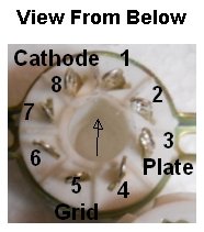
Plate is pin 3, Screen pin 4, Grid pin 5 and Cathode is pin 8. Heaters are on pins 2 and 7. Arrow points to the insertion index notch. Pin numbers start after the index notch and increase clockwise around the socket.
The power tube pins 3 (plate) and 4 (screen) should have high voltage DC and pin 5 (grid) should pop when probed with the meter. For fixed bias amps the grid should show a negative voltage but cathode biased amps will indicate near 0 volts on the grid. Pin 8 (cathode) will show 0 volts in fixed bias amps or show voltage between 10 to 25 volts DC in cathode biased amps. Nine pin power tubes like the EL84 have different pin functions so Google their data sheet to see their pin functions. With all the volumes turned up you should always hear a pop when probing the grid of any tube in the signal chain. Tubes that run the reverb or tremolo may not pop when probed.
If you get no grid pop then you have a problem somewhere between that tube and the last tube that popped. The first thing to try is to replace the tube. Next measure the voltage at every pin of the troubled tube's socket for clues to the problem.
Higher than normal voltage on the plates can be caused by no electron flow through the tube. This can be caused by no heater voltage or a disconnect between the tube cathode, the cathode resistor (if used) and ground. High voltage on the plates can also be caused by a higher value cathode resistor like using a 15k resistor instead of the specified 1.5k.
Lower than normal voltage on the plates is caused by too much current flow through the tube. This can be caused by an incorrect bias voltage on the grid. A leaking coupling cap can let DC voltage through to the grid and heat up the bias current. A lower value cathode resistor can also allow too much current to flow through a tube.
Cathode biased power and preamp tubes should show the bias voltage on the tube's cathode pin. If there is voltage on the plate but the cathode is zero this can be caused by a bad cathode resistor connection or no heater voltage. With the amp off measure the resistance from the cathode pin to ground. It should equal the cathode resistor value.
Fixed bias power tubes should show the cathode as connected to ground and show a negative voltage on the grid, usually between -30 to -50 volts DC. An incorrect grid bias voltage can make an amp sound bad.
Unwanted Grid Voltage Most preamp tubes should show no voltage on their grids (12A*7 tubes' pins 2 & 7) except tubes that function as phase inverters or cathode followers where voltage on the grid is normal. If the preamp tube's grid leak resistor is tied directly to ground it should not have any voltage on it. If there is voltage on the grid it's usually caused by a leaky upstream coupling cap (that must be replaced) or grid current. To verify the source of grid voltage you can pull the tube and see if the voltage on the tube socket grid pin goes away. If the grid voltage is still present then it's coming from a leaking capacitor or a wiring mistake. No voltage on the grid pin means the unwanted grid voltage was being generated by grid current. Try another tube and look for incorrect component values or wiring mistakes associated with that tube circuit.
Blown power tube screen resistors are a common cause of weak or nasty sounding output. When a power tube blows it often shorts the tube's plate to the screen which results in a blown screen resistor. A blown screen resistor will normally fail open with infinite resistance. The amp can operate with one power tube but it will sound weak and funky. When you replace the blown tube it will still function poorly because the blown screen resistor will not allow any voltage to the screens so the amp will sound different than with a blown tube but still not sound good due the huge output imbalance between the good tube and the tube with no screen voltage. Verify the screen voltage and the resistance across the screen resistor.
If the first power tube checks out then move to the next tube up the circuit which will be another power tube for push-pull circuits or the driver tube for single ended amps. Make sure all the volumes, gains and master volumes are turned up a little when you check the preamp tubes so you can listen for a pop when probing the preamp tubes' grid.
Again listen for a pop when probing the grid and plate pins and look for voltage anomalies. The pop should get louder as you test each tube up the amplification chain toward the input. Continue moving toward the first preamp tube. If you don't get a pop, or a weaker pop than expected when probing a tube's grid then you have found a problem area. Carefully check the voltages of that tube to find clues to why it's not working.
For 9 pin preamp tubes verify 5.7 to 6.9v AC between the heater pins 4 and 9, and 5 and 9 and verify you have DC voltage on pins 1 and 6 (plates), 3 and 8 (cathodes). You should hear a pop when probing the grids, pins 2 and 7. Nine pin tubes should have 0 volts on their grids unless the triode is being used as a phase inverter, cathode follower or uses grid bias.
If you have unexpected voltage on a tube's grid you may have a leaky coupling capacitor upstream allowing DC voltage through to the grid or a bad tube generating grid current.
Power Tube Red Plating
"Red plating" occurs when too much current flows through a tube. Too many electrons pound on the metal plates, heat them and make them glow red.
A bad tube can red plate so try another tube.
If your amp has two or more power tubes and only one tube red plates then move it to another power tube socket. If the same tube red plates in the new socket then the tube is bad. If the same socket red plates then we suspect the upstream coupling cap and a loose socket grid pin because we know the other socket has good bias voltage so the bias circuit is functional. Re-tension the grid pin of the red plating socket and test the upstream coupling cap.
If all the power tubes red plate then the problem is with the fixed bias circuit.
The tube's bias voltage, which is the voltage difference between the cathode and grid, controls the current flow through the tube.
If your amp has adjustable bias then measure the voltage on a power tube grid (usually pin 5 for 8-pin tubes) and adjust the bias pot for the largest possible negative voltage (usually around -60v DC) for the coolest bias. If this solves the red plating problem then adjust the bias and see if the problem remains solved.
If the power tube cathode has a connection problem the amp will stop passing current so the cathode usually doesn't cause bias and red plating problems so the grid is where we should focus our attention.
The fixed bias circuit is pretty simple so we want to closely inspect every solder joint and component with a magnifying glass.
Fixed bias amps need between -30 to -50 volts DC on the grid pins.
With the power tubes removed, power up the amp and measure the power tube grid voltages on all the tube sockets. This is pin 5 on typical 8-pin tubes.
If your amp has adjustable bias then set the highest negative voltage possible, usually around -60 volts. This will give us the coolest bias possible.
If you can't set a bias voltage between -40 to -60v DC then you may have a leaking coupling cap just upstream of the power tube grid. Un-solder one end of the coupling cap and see if you can set a bias voltage of -40 to -60v. This is especially true if you get different bias voltages on the power tube sockets. If nothing changes after lifting the coupling cap then the cap isn't the problem.
In the bias circuit we should have AC voltage where the power transformer connects to the circuit. We should have negative DC voltage after the bias diode. Move downstream and follow the negative DC voltage all the way to the tube socket. If you find a break in the voltage then look for the cause.
A bad solder joint, cracked resistor, dead, disconnected or reversed filter cap and bad bias pots can cause bias problems. A short to chassis will also kill the bias voltage. Gently push on bias components with a chopstick and look for movement due to loose solder joints or component cracks.
A loose socket grid pin can prevent bias voltage from getting to the tube which will cause instant red plating. Re-tension the tube socket pins.
Troubleshooting Spring Reverb
The reverb driver tube is pushed very hard with high voltage in many amps so the tube tends to burn out sooner than all the other small tubes. A bad tube can also cause excessive hum in the reverb. Swap out both reverb tubes with known good tubes and test the amp.
The reverb tank cable connectors (all 4 of them) can corrode and cause hum, pops, crackling, weak or no reverb. Clean the connectors (male and female) with contact cleaner. Spray the male connectors and insert them into the female connectors several times. If the connectors are heavily corroded a toothbrush, small brass brush or steel wool may be needed to get them clean.
Try another set of tank cables. They can cause intermittent signal drop out.
Mixing up the reverb input and output cables will result in very weak reverb. Swap the cables at the tank and try again. If it doesn't help or lowers reverb volume then swap the cables back.
The fine wires in the reverb tank are a common failure point and they are difficult to repair. Replace the tank if any of the wires are broken. I'm a fan of the MOD tanks for around $20.
If you bang on the side of the cab with the power on and reverb turned up and hear the reverb spring crash you know the reverb tank's springs, output transducer and reverb recovery amplifier are functioning (the second half of the reverb circuit).
You can switch the tank's input and output cables and bang on the amp again. If you hear the spring crash (it will be quieter this time) you know the input transducer is working. After this test you will know the problem is upstream of the tank, which is the reverb driver circuit including the reverb transformer. Swap the tank cables back to normal.
Test the reverb driver by verifying the voltage on the driver tube plate pins. For blackface and silverface amps the voltage should be around 400VDC (volts DC). If there is no voltage on the plate then try replacing the reverb driver tube. If that doesn't fix the problem then replace the reverb transformer.
Test the reverb driver and reverb transformer by connecting an 8 ohm speaker to the reverb transformer secondary wires. When you play through the amp you should hear a fairly loud clean guitar signal through the speaker. If not, then the problem is probably the reverb driver tube or the reverb transformer.
Loose transducers can cause funky problems. If they are loose put some glue on them to hold them solid or just replace the tank. MOD replacement tanks are my favorites.
Isolating the reverb pan with a pan bag, rubber grommets and foam padding between the cab and pan can help cure reverb problems, especially those that occur at high volume and high reverb settings.
Adding a noise cap to the reverb circuit can sometimes quiet a noisy reverb. See this for more info.
A weak or bad V4A (Reverb Recovery) cathode bypass cap can cause a reverb oscillation (squeal) due to positive feedback between V4A and V4B (Vibrato channel third gain stage).
A bad pan ground can cause the reverb intensity knob to add volume and gain (add dirt). Check cables and cable plugs and sockets.
Reverb Hum
Try turning the reverb pan 180 degrees to reduce interaction between the power transformer and the pan's output transducer.
There are many reverb pan grounding schemes and an incorrect set of cables can lift the pan's ground or cause a ground loop. Look at your amp's schematic to verify what part of the tank and cables should be grounded and what shouldn't.
Temporarily clip a ground connection to the tank and see if that helps with the hum.
See How Spring Reverb Works for more info.
"Chopsticking" the Amp
You can use a non-conducting wooden chopstick to move wires around with the amp on and all the volumes up to identify lead dress problems which can cause hum and oscillation. On my first amp build I had the V1A plate and grid wires lying on top of one another which created a moderate hum. Simply moving those wires apart made the amp almost silent. A chopstick can also be used to apply pressure to components and solder joints to identify weak components and joints. You can also lightly tap on tubes to identify microphonic tubes. Don't forget to chopstick the speaker cable connections.
Freeze Spray for Intermittent Problems
Intermittent problems are sometimes caused by a weak component or bad solder joint that is affected by heat as the amplifier warms up. You can sometimes identify the issue by waiting for the problem to occur then carefully spray freeze spray to cool amp components and solder joints. If spraying a part or solder joint causes the issue to go away or come back you've located the problem.
Break Out the Oscilloscope
For really tough troubleshooting tasks I break out the tone generator and inject a 500Hz 100 milliamp (.1 amp) signal at an amp's input jack and trace it through the amp with an oscilloscope by probing the tube grids. Start at the input jack and work towards the speaker and watch for the wave shape to disappear or change shape. There are tone generator apps for your phone but you will need an adapter with a 1/4" mono TS plug to plug into the amp's input jack. You will risk your $600 dollar phone every time you plug in though. You can play a single string on a guitar to generate a waveform but it's kind of a pain in the butt and a guitar's harmonics and timbre will make it harder to spot anomalies on the scope.
I also use a dummy load when doing this test so I don't have to listen to the damn tone coming through the amp's speaker. Be careful with your oscilloscope probe because the very high voltage on the tube plates can damage it unless you use a high voltage rated probe. The grids normally have zero or low DC voltage so I take my signal sample from the grids unless I really need to examine the plate signal.
When searching for low-level noise turn down the tone generator signal to around 5 millivolts (.005 volt) to make seeing the noise easier in the early preamp stages. The tone generator signal will be a smooth sine wave on your scope. The noise can be just a little "hair" or small spikes on the tone signal wave.
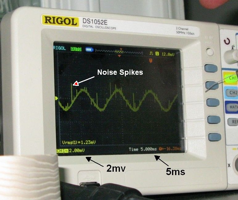
60 Hz signal with noise spikes.
Oscope Basics
Set the oscilloscope to AC coupling. It's safest to connect the scope probes to the amp chassis with the amp's power off.
Examine the amp from amp input to output and look for the tone generator or guitar signal to change shape (distort) or disappear (loss of all sound).
To examine the guitar or tone generator signal before amplification clip the scope probe onto the input jack center conductor and the probe ground clip to the preamp ground bus. This will be the smallest, lowest voltage signal you will encounter. Amplification through the amp will make the signal larger (higher voltage).
Adjust the scope time and voltage setting knobs until you can see at least one full wave on the screen. If you set the scope's trigger line to just above zero volts the signal wave should stabilize on the screen (the trigger line needs to touch the on screen signal to stabilize the signal for viewing).
To see the signal at the first gain stage grid move the probe to the tube socket grid pin. Tube grids are usually at zero volts DC (phase inverters and cathode followers can have up to 80v DC) so grids are safer to probe than plates which can have over 500v DC on them.
Move the scope probe to the second gain stage grid and increase the scope's voltage setting knob to shrink the signal to fit on the scope screen.
When probing the power tubes move the scope probe ground clip to the power amp ground.
Oscope Tips
Pay attention to the max AC & DC voltage ratings of your scope and probe. This is especially important when probing tube plates with high voltage DC on them.
Set the scope to AC coupling. This inserts a cap between the probe and scope circuit to keep high voltage DC out of the scope.
Set the X10 switch on the probe if needed for higher voltage signals. With the X10 switch on a 100v signal will show as 10 volts on the screen.
Clip the ground clip to an appropriate ground point with the amp turned off. For example use the preamp ground bus or last filter cap ground when probing the preamp and use the power amp ground or first filter cap ground when probing the power amp.
When chasing an oscillation or other signal artifact it can be helpful to disconnect the global negative feedback because NFB will try to correct and minimize the oscillation or artifact.
Stop Tremolo Ticking
The very strong tremolo oscillator signal can induce ticking into the amp's signal stream. First try to separate the tremolo driver plate (V5 pin 6) wire from any grid wires to stop the ticking. Pay close attention to the nearby V6A phase inverter grid (pin 2) wire.
Another option is to use a shielded cable like RG174 for the tremolo driver plate wire (V5 pin) to stop the transmission of the tremolo signal. This is almost a 100% fix for tremolo ticking. Ground the cable shield at only one end (either end) to prevent a ground loop.
If the above don't work then adding a .02uF cap to the tremolo roach should stop it.
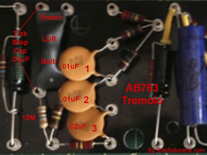
Add a .02uF 400v (or higher voltage) cap across the left side of the tremolo roach to cure tremolo tick.
See this to slow the tremolo.
Testing Diodes
To test a diode make sure the circuit is powered down (drain the caps) and measure the diode's resistance both ways across it (measure, then reverse the meter probes, measure again).
A good diode will show resistance of 7 to 15 ohms in one direction (forward resistance) and almost infinite resistance in the other direction (reverse resistance).
Reading an open circuit (infinite resistance) both ways means the diode is open.
A zero resistance reading in either direction means the diode is shorted.
A diode with a resistance reading below 7 ohms should be replaced.
Measuring a series of diodes in a row should show about 12 ohms of resistance per diode in one direction and infinite resistance in the other.
The striped end of a diode is the cathode end, the other end is the anode.
If you'd like to help with the
cost of running this graphics heavy website you can make a
PayPal donation to![]()
By Rob Robinette
References
RCA Corporation, RCA Receiving Tube Manual, RC30.
Merlin Blencowe, Designing Tube Preamps for Guitar and Bass, 2nd Edition.
Merlin Blencowe, Designing High-Fidelity Tube Preamps
Morgan Jones, Valve Amplifiers, 4th Edition.
Richard Kuehnel, Circuit Analysis of a Legendary Tube Amplifier: The Fender Bassman 5F6-A, 3rd Edition.
Richard Kuehnel, Vacuum Tube Circuit Design: Guitar Amplifier Preamps, 2nd Edition.
Richard Kuehnel, Vacuum Tube Circuit Design: Guitar Amplifier Power Amps
Robert C. Megantz, Design and Construction of Tube Guitar Amplifiers
Neumann & Irving, Guitar Amplifier Overdrive, A Visual Tour It's fairly technical but it's the only book written specifically about guitar amplifier overdrive. It includes many graphs to help make the material easier to understand.
T.E. Rutt, Vacuum Tube Triode Nonlinearity as Part of The Electric Guitar Sound