[ How the 5E3 Deluxe Works ] [ Deluxe Models ] [ DRRI & 68 CDR Mods ] [ My 5E3 Build ] [ The Trainwreck Pages ] [ Fender Input Jacks ] [ B9A Prototype Boards ]

Fender 5F6-A '59 Bassman Amplifier Info and Modifications
By Rob Robinette
Have comments or corrections? Email rob at:
![]()
WARNING: A tube amplifier chassis contains lethal high voltage even when unplugged--sometimes over 700 volts AC and 500 volts DC. If you have not been trained to work with high voltage then have an amp technician service your amp. Never touch the amplifier chassis with one hand while probing with the other hand because a lethal shock can run between your arms through your heart. Use just one hand when working on a powered amp. See more tube amplifier safety info here.
I don't expect anyone to mod their original 5F6A Bassman but if you have a Bassman reissue or home build like me then adding some switchable mods can be beneficial. I'm not trying to improve the 5F6A so much as I'm trying to make the amp more versatile. Some of the mods work well together too. When I need more headroom I'll flip the feedback switch to the JTM45 position but this pairs well with the preamp gain boost switch which adds more preamp gain. The switch allows you to tweak the balance between preamp and poweramp distortion. I also find myself using the raw (tone stack cut) switch quite a bit too. It give's me an instant, known standard tone at the flip of a switch.
Most of these mods apply to the almost identical Marshall JTM45 also.
Most of the mods below are on a switch so you can deactivate the mod. I absolutely love my 5F6A and encourage everyone to build or buy one.
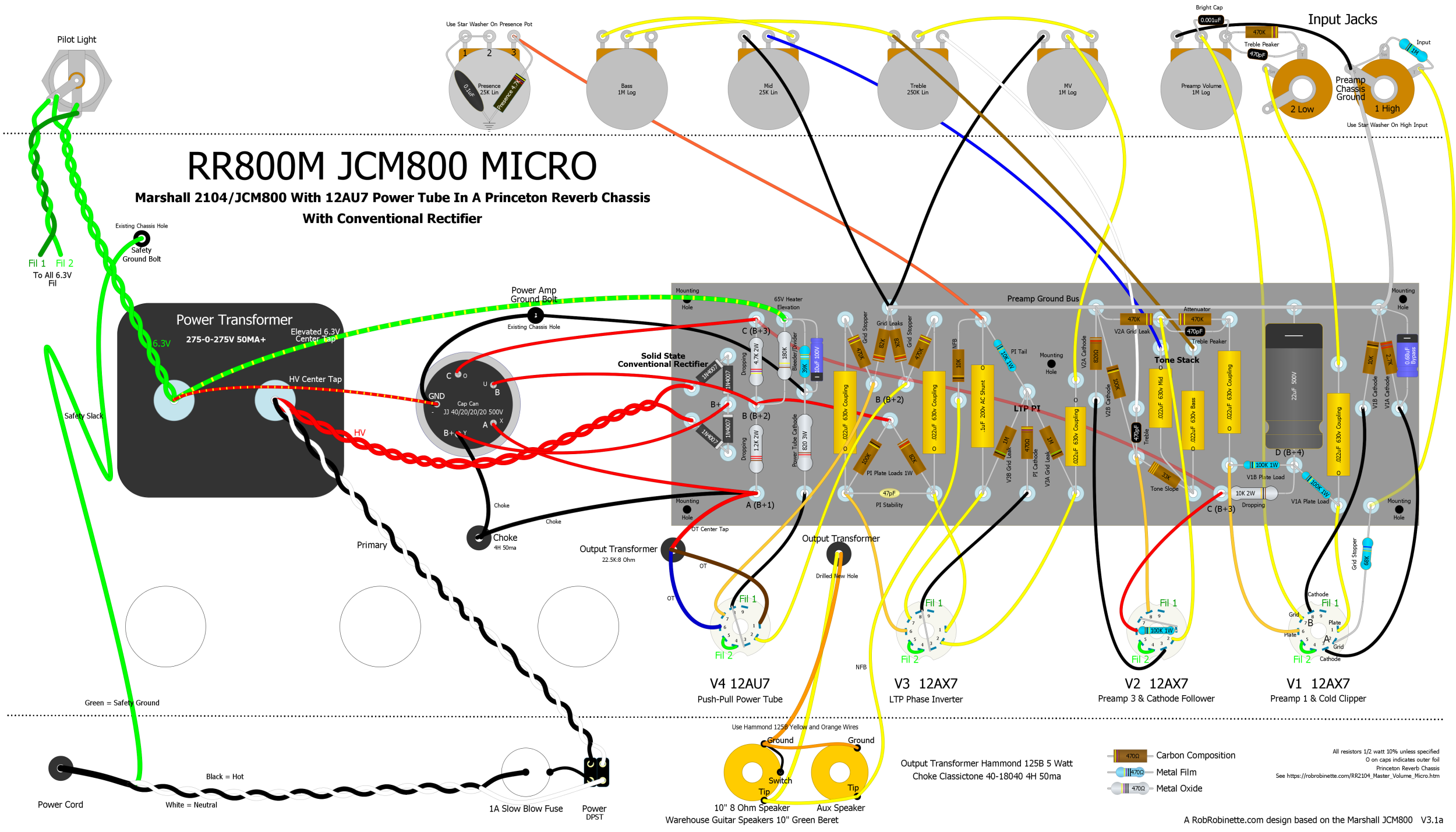
Modern 5F6A Bassman Layout
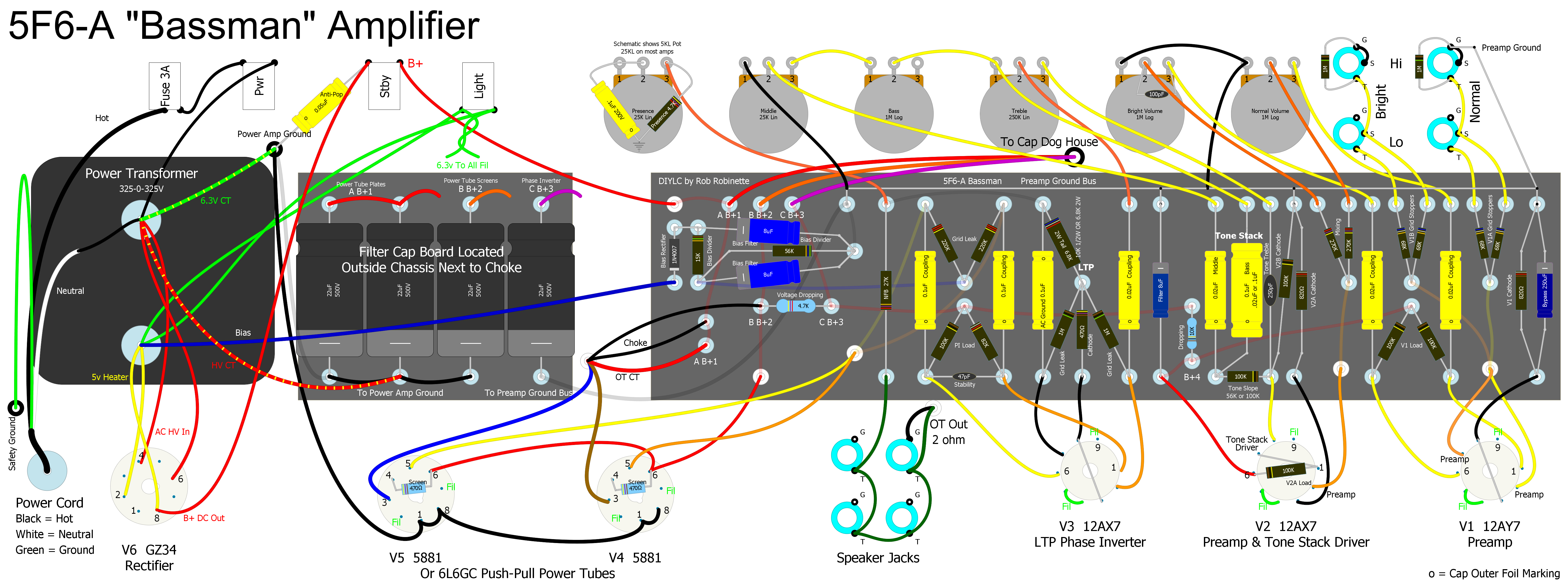
Differences from the original Fender 5F6A layout: Ground switch is deleted, 3-Prong power cord, balanced 6.3v heater wiring, diode bias rectifier added, split Power Amp and Pre Amp Ground Bus, Capacitor Board is shown. The Cap Board is usually located outside the chassis in a 'dog house' next to the choke. Most original 5F6A amps came from the factory with a 100k Tone Slope resistor, .1uF Bass Tone cap and 6.8k Phase Inverter Tail resistor. Click the image to see the full size readable layout. Click the above image to see the hi-res version. Click here for a hi res pdf. Click here to download the 5F6A DIYLC file.
Annotated Schematic With Signal Flow and Component Function

What do all those parts do? Click on the graphic to see the full size and readable schematic. This original schematic does not reflect the changes made to most production 5F6A amps. Those amps had a Tone Slope resistor of 100k, Bass cap of .1uF, Phase Inverter Tail resistor of 6.8k 2 watt and the Presence circuit is the same used in the 59 Reissue.
List of Mods
3-Way Negative Feedback Switch: My favorite 5F6A mod. Normal / 5E3 / JTM45 selectable feedback.
Adjustable Bias: Adjust your power tube bias for max output and sweetest tone.
Adjustable Balanced Bias: Adds a second bias pot to the Adjustable Bias circuit to evenly bias unmatched power tubes.
High Voltage Tap Adjustable Bias: Tap your center tapped power transformer to create a 50v bias tap.
High Voltage Tap Adjustable Bias for Bridge Rectifiers: Tap your bridge rectifier to create a 50v bias tap.
Tube / Solid State Rectifier Switch: Saggy or firm rectification at the flip of a switch.
Raw (Tone Stack Bypass) Switch: Remove all traces of the tone stack at the flip of a switch for pure (raw) guitar tone.
Raw Control: Allows variable tone stack bypass.
Voice a "Lead" Channel: Tighten up and modernize one channel's clean and overdrive tone.
Master Volume: Get overdrive at lower volume and control power tube overdrive.
Master Volume + Vox Cut Control: I love this thing.
One Wire Cascade: This old JTM45 mod will cascade the Normal channel into the Bright channel for a high gain preamp.
Add an FX Loop: This is where you do it.
Preamp Local Negative Feedback This simple little mod can help tune the overdrive tone.
3-Way Preamp Bias Switch: Hot - Cool - Normal preamp tube bias with and without bypass caps.
Channel Jumper Switch: Leave your patch cord at home.
Fixed / Cathode Bias Switch: Standard 5F6A or 5E5 Pro style round tubey warmth and compression.
Gain Boost Switch: Add more preamp gain for more dirt.
Pentode / Triode Half Power Switch: Cut your output wattage in half.
EL34 Compatibility: Go Brit with EL34 power tubes.
Run 6V6 Power Tubes: Less output power, small bottle tone with more power tube distortion.
Power Tube Grid Stopper Resistors: Add power amp stability and decrease blocking distortion.
Reduce 'ice pick' Highs: If your speakers are too shrill this simple, subtle cap can help.
Line Out Jack: Simple way to feed the PA and recording rig.
Simulate Tube Rectifier Voltage Drop and Sag Using a Solid State Rectifier and Sag Resistor
Lower the B+1 Voltage: Higher wall voltage can lead to high amp voltages.
Lower the Heater Voltage: Keep your tubes in their sweet spot.
Standby Switch 'Pop Reduction' and Current Inrush Surge Protection
6.3v Artificial Center Tap: Reduce 60Hz heater hum.
Humdinger Heater Hum Pot: Adjust this pot to minimize 60Hz heater hum.
LED Pilot Light: Simple LED circuit using 6.3v heater power
Amp Protection Mods: Protect your Bassman from expensive damage.
Using the Ground Switch Hole for Mods: Be careful, it's noisy over there.
Add a 6" practice speaker to your amp head.
The 5F6A's TMB Tone Stack mounted on three pots.
5F6A Bassman Info
Considerations before building a 5F6A
Build a 3 tube Bassman Micro 2 watt practice amp.
How the Long Tail Pair Phase Inverter Works
Fender Mid-Production Circuit Changes Two resistor tweaks, a cap change and modified presence circuit make for a major tone change.
Download the Duncan Tone Stack Calculator and 5F6A Bassman file
5F6A Power Transformer Calculations
Differences between the 5F6A Bassman and its clone, the Marshall JTM45

3-Way Negative Feedback Switch
This is my favorite and most useful 5F6A mod, a three-way SPDT ON/OFF/ON mini-switch gives you: Normal 27k (2 ohm tap) feedback resistor / No Feedback / JTM45 equivalent 10k feedback. The 'No Feedback' position makes the amp break up early kind of like a 5E3 Deluxe. Combine this position with the Gain Boost Switch and you have a virtual 5E3. The Marshall JTM45 was a direct copy of the 5F6A but the feedback signal was tapped from the 16 ohm output transformer secondary instead of the 5F6A's 2 ohm secondary resulting in the JTM45 getting 2.8 times more feedback. The 10k feedback resistor (27k / 2.83 = 10k) in this mod will triple the amount of feedback compared to the 5F6A's 27k feedback resistor giving you a JTM45 level of feedback.
The extra feedback makes the cleans cleaner and tightens up the boundary between clean and overdrive which can make it easier to control overdrive with finger technique. More NFB also tightens up the low end and increases the amp's damping factor.
Install a 12AX7 in V1, select JTM45 negative feedback and play through a Marshall stack and you'll get a very Marshallesque tone. Swap in a pair of KT66 power tubes and you're there.
If your 5F6A feedback is tapped off an 8 ohm speaker output like mine then your 5F6A feedback resistor should be 56k to give the same amount of feedback as the original 5F6A's 2 ohm output with a 27k feedback resistor. You should use a JTM45 equivalent resistor of 20k.
If your feedback is tapped off a 16 ohm speaker tap then your feedback resistor should be around 75k, so use a JTM45 feedback resistor of 27k. When changing the feedback source from one output transformer secondary to another you change the feedback resistance by a factor of 1.41 for one step change ( for example going from a 2ohm speaker tap to 4 ohm), a factor of 2 for 2 steps (example 2 ohm to 8 ohm), or a factor of 2.83 for 3 steps (example 2 ohm to 16 ohm).
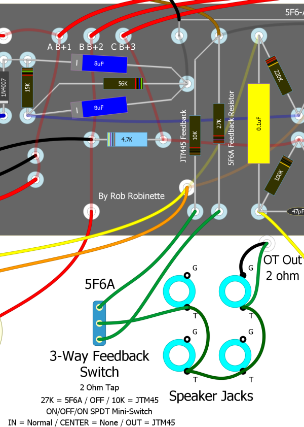
I put the NFB switch next to the speaker jacks for short wire runs.
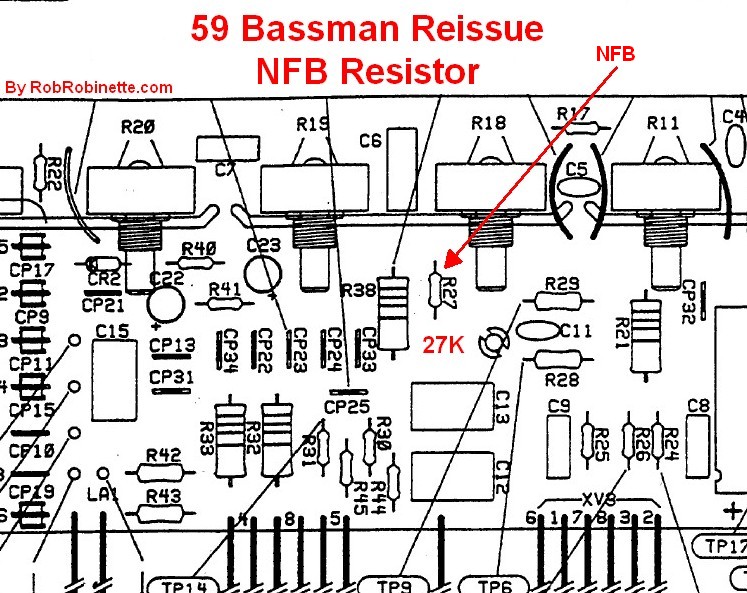
R27 is the NFB resistor.
Speaker Tap and Feedback Levels
|
Speaker Tap |
5F6A Light Feedback |
Moderate |
JTM45 Heavy |
|
2 ohm |
27k 5F6A |
20k |
10k |
|
4 ohm |
39k |
27k |
13k |
|
8 ohm |
56k |
39k |
20k |
|
16 ohm |
75k |
56k |
27k JTM45 |
Moderate is 41% more feedback than Light. Heavy is 2.8 times more feedback than Light.
Adjustable Bias
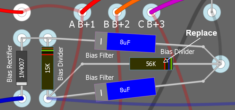
To make the 5F6A's bias adjustable you simply replace the bias circuit's 56k resistor (connected to 15k resistor and ground) with a mini-50k linear pot (or trim pot) and 27k resistor. This mod also allows you enough adjustment range to bias 6V6, 6L6, EL34, KT66, KT77 and KT88 power tubes.
The 15K and 56K resistors in the original bias circuit form a voltage divider to reduce the voltage coming out of the bias rectifier diode. The two 8uF caps are filter caps to smooth out the pulsing DC from the bias diode.
My Mercury Magnetics power transformer puts out 60 volts AC for the bias circuit where approximately 50v is the norm so I had to use a smaller 24k resistor to bleed off more bias voltage to get the bias hot enough to reach 70% idle dissipation. The 24k resistor gave me plenty of pot movement to bias a variety of tubes. If you find you run out of room and need to get a hotter bias then decrease the value of the resistor. If you need more room on the cool bias end then increase the value of the resistor.
As you turn the pot clockwise the bias will get hotter (higher dissipation) as the negative bias voltage on the control grid will decrease toward 0v. For a new amp startup I recommend presetting the bias pot full down (counter clockwise, coolest bias). It's also a good idea to turn the bias down some before installing a new set of tubes and then bias them immediately upon power up. Always watch new power tubes for red plating upon first power up.
My Tung-Sol 5881 power tubes biased at -45.1v on the grid, 443v plate, 40.7 milliamps (measured by OT shunt) for 69.3% of their rated 26 watts of plate dissipation. A set of JJ KT88's biased at -45.5v on the grid, 430v on the plates and 55ma of plate current for 68.7% of their rated 35 watts. That's with a JJ GZ34S rectifier tube. The Fender 5F6A schematic shows -48v as the bias voltage for 5881 tubes which would yield a significantly cooler bias.
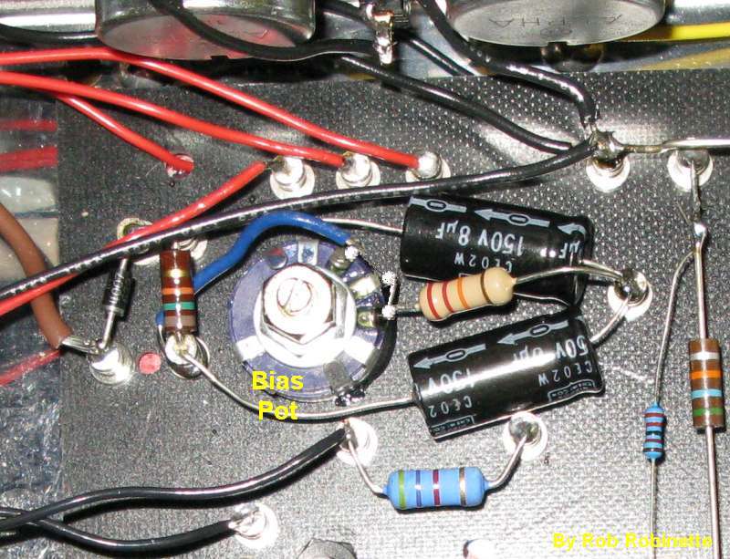
I glued my bias pot to the circuit board as shown in the layout below but you can mount it anywhere. Just run the blue bias wire to the bias pot's #3 terminal, connect the 27k resistor to the center (wiper) #2 terminal and use the resistor's lead to form the jumper to terminal #1. Then ground the other end of the 27k resistor at any convenient ground. Many people put the bias pot in one of the unused speaker jack holes. If you make the bias pot accessible from the amp's exterior I recommend you use a screwdriver slotted pot or this one to make it more difficult to accidentally alter the bias.
For an interior access only bias pot I highly recommend this Bourns 50k multi-turn trim pot part # 3299Y-1-503LF. At 50k it will offer a wide range of adjustment and since it's a multi turn trim pot it is very precise too.
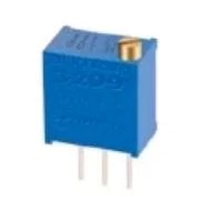
Bourns 50K multi-turn trim pot.
Standard Non-Adjustable Bias
Adjustable Bias
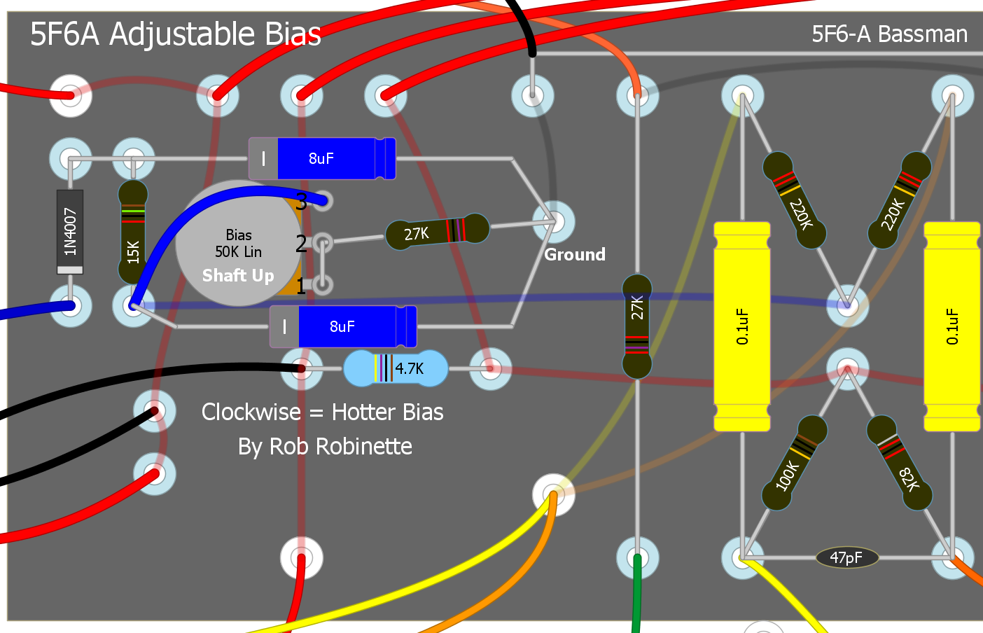
The bias pot wired as a variable resistor and 27k resistor replace the 56k resistor above.
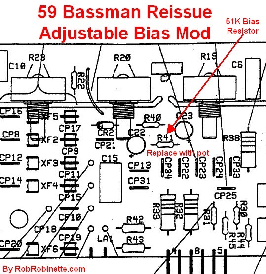
R41 Bias Resistor is 51k.
How I Did It
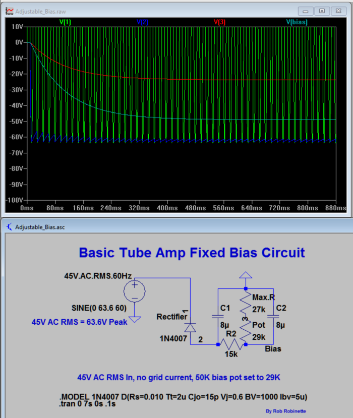
LTSpice model of the standard 5F6A bias circuit. Bias voltage is plotted in light blue, transformer voltage is green, diode output is dark blue and red is the junction of the pot (set a 29k) and 27k resistor (56k total resistance). The bias voltage stabilized at -49v.
Adjustable Balanced Bias
This mod uses two bias pots so you can set the bias for each power tube. This allows you to use unmatched tubes but bias them evenly. You can even run a 6V6 and a 6L6 power tube together and bias each tube properly. You can also fatten up the clean and overdrive tone by intentionally mismatching the two tubes' bias which increases harmonic distortion. An increased bias mismatch can cause an increase in hum so keep an ear out for that if you dial up an intentional mismatch.
5F6A Adjustable Balanced Bias
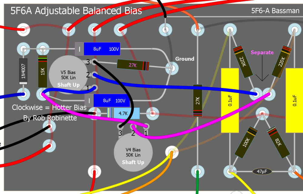
Note you have to separate the two 220k power tube grid leak resistors to give each one their own bias supply. Increasing the value of the two 8uF filter caps can help reduce 60Hz hum. I like to use 100uF 100+ volt capacitors.
One way to separate the two 220k power tube grid stopper resistors is to de-solder them from the turret. Then use 20 to 24 gauge solid core wire (solid core so it will stay in place) to run from the bias pots' center wipers to the now empty turret. Put two wraps each around the turret for support (leave the wire insulation on for the wraps) and solder each resistor to a wire end.
The 27k bias resistor sets the maximum hot bias. If at full clockwise pot movement (max hot bias) you still need to bias hotter then reduce the value of the 27k resistor--try 24k or 20k. If at full counter-clockwise pot movement (min cool bias) you need to bias cooler then increase the value of the 27k resistor to 30k or 36k.
High Voltage Tap Adjustable Bias for Center Tap PT
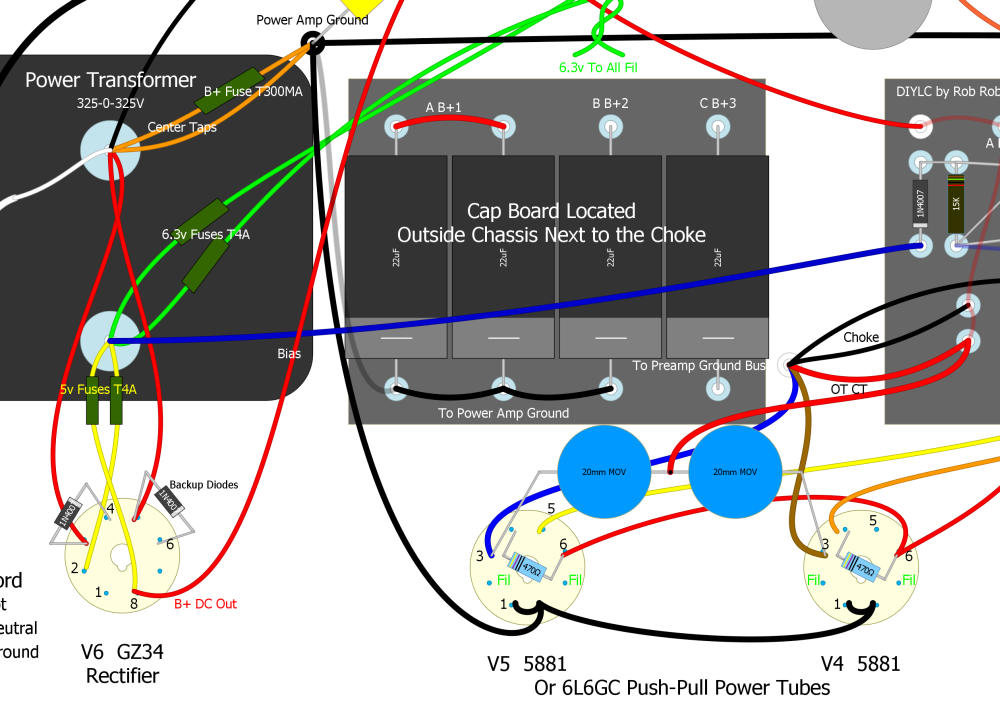
You can use this circuit that's loosely based on the Marshall JCM800 to create an adjustable bias tap without using a power transformer with a dedicated 50v bias tap.
This circuit is designed for use only with power transformers using a center tap and conventional rectifier. See the next section below if your amp has a bridge rectifier.
You tap high voltage AC from the rectifier tube and create an adjustable bias circuit. This is a universal circuit that can be used on pretty much any amp. Turning the bias pot clockwise will make the bias hotter (more plate current). A 50k linear pot or trim pot offers lots of adjustment range so this circuit can bias everything from the 6V6GT to KT88's and it isn't picky about the AC input voltage level.
If you end up needing a cooler bias than the circuit provides you can reduce the 220k resistor (try 180k or 150k) for more room on the cool side of the adjustment range. If you need more room on the hot side then increase the 220k resistor to 240k or 270k.
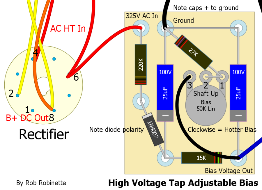
Note the two 25uF 100 volt filter caps have their + terminals connected to ground because the circuit is dealing with negative voltage. Be sure and get the 1N4007 diode's polarity right with its stripe facing the power transformer. The bias pot is shown shaft up. All resistors are 1/2 watt rated. The black wire at the top goes to ground. The blue wire at bottom right carries bias voltage out to the power tube grid leak resistors.
The two filter caps can be anything from 10uF to 50uF, and 100 volts and up. For the bias pot you can use a normal type pot, a screwdriver slotted pot or a trim pot.
How It Works
High voltage AC from the power transformer enters the circuit at the 220k voltage dropping resistor. The diode acts as a half-wave inverter creating 60Hz pulsed negative voltage DC (simply turning the diode around would give you positive voltage). The pulsing negative DC is filtered by the two 25uF filter caps and 15k resistor. The caps and resistor form an RC (resistance capacitance) low pass filter to smooth the DC and remove the 60Hz ripple current. The bias pot and 27k resistor form a variable resistor that when combined with the 15k resistor create a variable voltage divider. Lowering the bias pot resistance sends more voltage to ground which moves the output DC bias voltage closer to 0 volts which allows more power tube bias current to flow making the bias hotter.
JCM800 Bias Circuit
My circuit increases the value of the two filter caps to reduce hum and reverses the value of the pot and resistor to increase the bias range to work with more amps and tube types.
High Voltage Tap Adjustable Bias for Bridge Rectifiers
You can use this circuit that's based on the Marshall JCM900 to create an adjustable bias tap without using a power transformer with a dedicated 50v bias tap. This circuit is designed for use with bridge rectifiers with no center tap. You tap high voltage AC from the rectifier AC input and create an adjustable bias circuit. This is a universal circuit that can be used on pretty much any amp with a bridge rectifier. Turning the bias pot clockwise will make the bias hotter (more plate current). A 50k linear pot or trim pot offers lots of adjustment range so this circuit can bias everything from the 6V6GT to KT88's and it isn't picky about the AC input voltage level.
If you end up needing a cooler bias than the circuit provides you can increase the 47k resistor (try 51k or 56k) for more room on the cool side of the adjustment range. If you need more room on the hot side then decrease the 47k resistor to 43k or 39k.
This circuit is designed for use only with bridge rectifiers (no power transformer center tap). See the section above if your amp has a center tapped power supply.
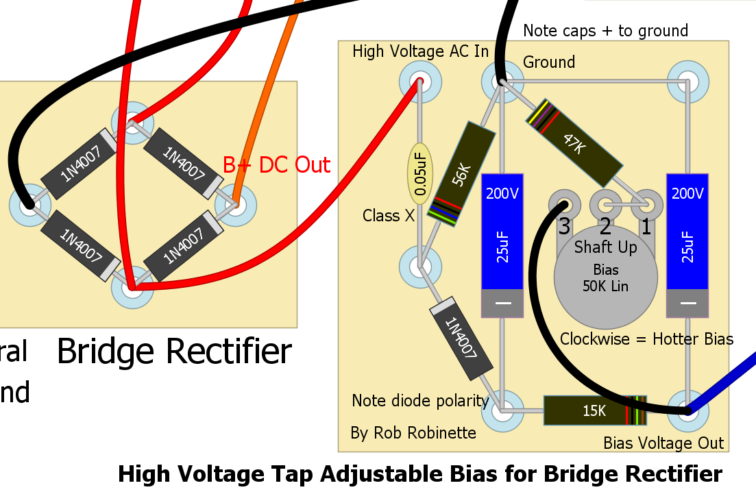
Note the .05uF capacitor must be rated as Class X or Y. The two 25uF 200+ volt filter caps have their + terminals connected to ground because the circuit is dealing with negative voltage. Be sure and get the 1N4007 diode's polarity right with its stripe facing the rectifier. The bias pot is shown shaft up. All resistors are 1/2 watt rated. The black wire at the top goes to ground. The blue wire at bottom right carries bias voltage out to the power tube grid leak resistors.
This Vishay .05uF capacitor has a Class X safety rating meaning it is rated to be connected from 400V AC to ground. The two filter caps can be anything from 10uF to 50uF, and 200 volts and up. For the bias pot you can use a normal type pot, a screwdriver slotted pot or a trim pot.
How It Works
High voltage AC from the power transformer enters the circuit at the .05uF Class X capacitor (rated for use across mains voltage). This cap forms a voltage divider with the 56k resistor to reduce the input AC voltage. The 56k resistor also supplies the capacitor recharge electrons from its ground connection.
The diode acts as a half-wave inverter creating 60Hz pulsed negative DC voltage (simply turning the diode around would give you positive voltage). The .05 cap, 56k resistor and diode form an electron one-way valve. Negative AC voltage passing through the cap pushes electrons against the 56k resistor and through the diode creating a negative DC voltage at the diode's output. Positive AC voltage from the cap tries to pull electrons through both the diode and resistor but the diode won't allow it so electrons are pulled through the 56k resistor to charge the cap. This is repeated every AC cycle.
The pulsing negative DC put out by the diode is filtered by the two 25uF filter caps and 15k resistor. The caps and resistor form an RC (resistance capacitance) low pass filter to smooth the DC and remove the 60Hz ripple current. The bias pot and 47k resistor form a variable resistor that when combined with the 15k resistor create a variable voltage divider. Lowering the bias pot resistance sends more voltage to ground which moves the output DC bias voltage closer to 0 volts which allows more power tube bias current to flow making the bias hotter.
See the Marshall JCM900 schematic for a schematic view of this circuit. My circuit increases the value of the two filter caps to reduce hum and increases the value of the pot to increase the bias range to work with more amps and tube types.
See this to measure and adjust your amplifier's bias.
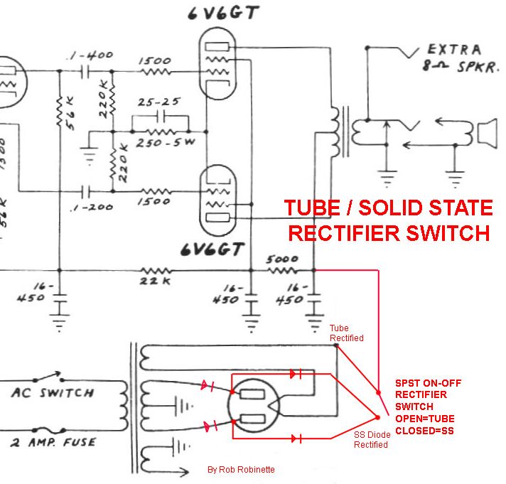
Tube / Solid State Rectifier Switch
This simple mod will give you the choice of normal tube rectification with it's inherent voltage sag or give you solid state rectification with its higher, stiffer voltage. Solid state rectification and its higher B+ voltage will make the amp a little punchier and modernize the tone slightly. The GZ34 tube rectifier only drops the voltage about 18 volts compared to solid state but you can use a tube rectifier with more voltage drop like the 5U4G with a 44 volt drop to emphasize the difference, but make sure your power transformer can supply 3 amps of 5 volt heater current (the GZ34 uses only 2 amps). The extra voltage drop of the 5U4G will lower all the amp's voltages, soften the tone and make the amp a little 'browner.' The extra rectifier voltage sag will affect the amp's dynamics and may enhance note 'bloom.' The solid state rectifier position works great with the 'JTM45' negative feedback mod and will help the tone sound more 'modern Marshall.'
If your amp is fixed bias and taps its bias voltage from the power transformer's high voltage secondary you must keep the bias tap BEFORE any diodes because the high voltage bias circuit must be fed AC voltage. If your amp is cathode biased or fixed biased with a separate power transformer bias supply wire then this mod will work without any modifications.
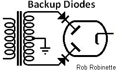
Rectifier Switch In a 5E3 Deluxe
Open switch = tube rectification, closed switch = solid state rectification. When the switch is closed the diodes' low voltage drop bypasses current around the tube rectifier.
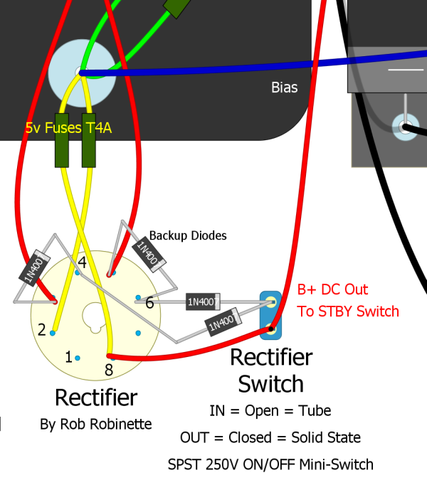
The 'Backup Diodes' mounted on the rectifier tube socket pull double duty. When using tube rectification they share the load with the tube rectifier and protect the amp from a rectifier tube short. When solid state is selected with the Rectifier Switch both sets of diodes work together to directly supply the rectified B+ . The second pair add share the load and add redundancy by protecting from a failed, shorted diode.
You can also use an ON-ON SPDT 250V mini switch. Connect the B+ output wire to the center switch terminal. Connect the diode rectifiers to one of the other terminals and connect the wire from tube pin 8 to the third terminal.
Here's a chart from 300guitars.com showing the different rectifier voltage drops:
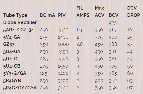
The 5Y3's current rating of only 125 milliamps would strangle a 5F6A but the 5R4 will work nicely. Note the 5 volt 3 amp heater current requirements for some of the tubes.
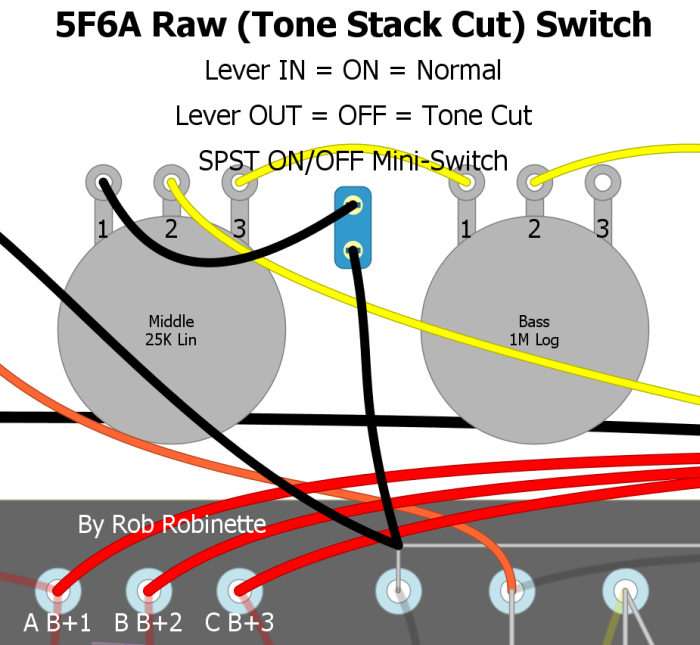
Raw (Tone Stack Bypass) Switch
This is a great mod for pretty much any amp with a TMB (treble mid bass) tone stack. Add an SPST ON/OFF mini-switch to the Middle tone pot's ground. No ground = no tone stack which gives you a very significant signal boost and pure "raw" unaltered tone. I find myself using this switch to instantly find a known, standard tone. It also works great with EQ pedals because it lets the pedal do all the tone shaping. I was surprised by how much of a signal boost I got with this switch engaged, even with all three tone controls at max. This is a simple and very worthwhile mod for any amp with a standard tone stack. You can also combine the Raw Switch with the Raw Control pot (next mod below) so you can fine tune the tone you get with this switch. I placed my Raw mini-switch between the Middle and Bass pots.
Raw Switch On and Off
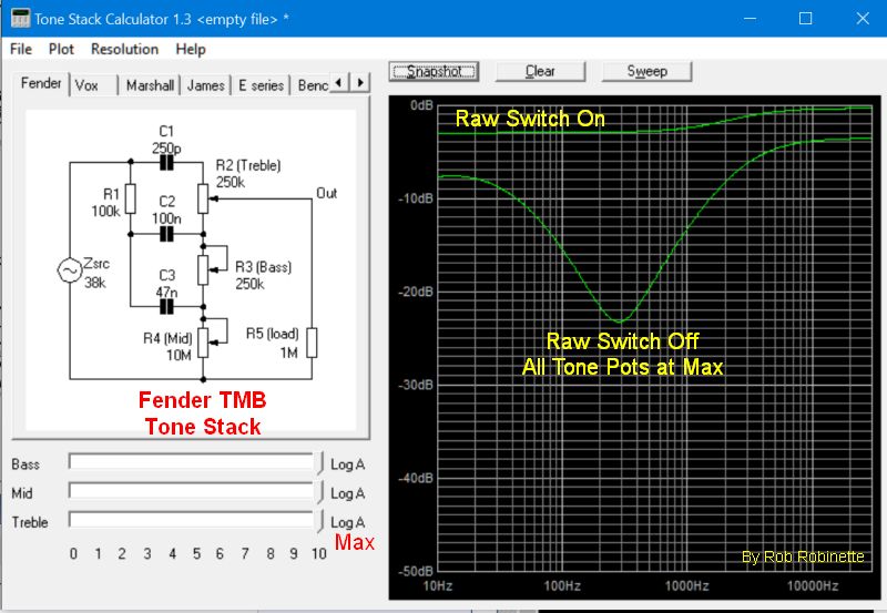
You can see how the mid scoop is flattened and what a huge boost in signal you get with the Raw Switch On (tone stack ground disconnected) even with all three tone pots at max. Chart is from the Duncan Tone Stack Calculator.
Be sure and take a close look at the presence pot ground wire. If it is connected to the mid pot you will need to give the presence pot its own connection to ground.
Remove the tone stack's ground and you completely bypass the tone stack.
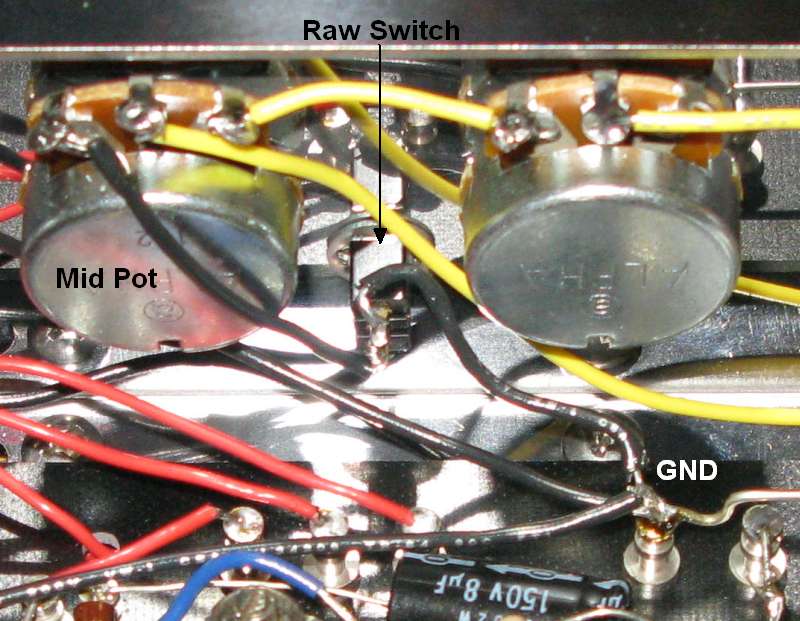
5F6A tone stack and Raw Control location.
I had one modder get an oscillation when he bypassed his tone stack with a raw switch. The extra gain from removing the lossy tone stack was enough to cause a downstream gain stage to freak out. He solved the problem by placing a 100k resistor across the switch terminals. The resistor reduces the gain jump when the switch is opened. You can use this resistor to fine tune the level of gain added when the raw switch is turned on (opened).
Raw Control
Replacing the 25K Middle pot with a 100KA audio pot will allow you to dial out the tone stack at higher Mid settings. With the Mid control set at 1 you get lots of headroom, Twin-Reverb like clean. At about 3-4 you get the normal 5F6A mid voicing. And at 10 you get full tweed - meaning the tone stack is almost completely eliminated from the amp circuit so you get a nice signal boost. This is a very simple remove-and-replace mod that is very worthwhile.
Be sure and take a close look at the presence pot ground wire. If it is connected to the mid pot you will need to give the presence pot its own connection to ground.
Trainwreck Type-2 & Type-3 Master Volume
The Trainwreck Type-2 is a very "transparent" master volume which virtually disappears when at max master volume setting. It is much more difficult to add to an existing amp so for modding an existing amp I recommend the Type-3 master volume.
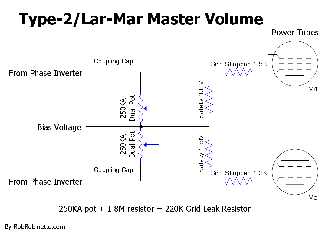
When the master volume is turned down the guitar signal is bled to ground through the bias circuit. The 1.8M Safety resistors allow bias voltage to pass around the master volume pot in case of a wiper failure. The resistors also lower the max grid leak resistance to 220k to match the stock grid leak resistors. If you can't find 1.8M resistors you can substitute 2M.
Type-2/Lar-Mar Master Volume
A dual gang 250KA pot (one shaft turns both pots, audio or log taper) replaces the two 220k power tube grid leak resistors. This is the most transparent of all the master volume types. The 1.8M resistors on the Master Volume pot reduce the pot resistance to 220k (the stock value) and add a failsafe path for bias voltage.
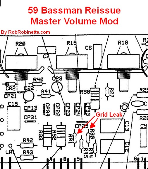
R30 & R31 are the 220k power tube grid leak resistors. The top of the resistors are connected to the bias circuit, the bottom are connected to the power tube grid stopper resistors.
There are many master volume options but the Type-3 is very easy to install and it works as well as any other master volume I've tried in any of my amps. This master volume controls the signal level feeding the power tubes so you can use it for lower volume distortion and to control the balance between preamp and power tube distortion. It works by mixing the two phase inverter output streams together and they cancel each other out. Less resistance = more signal mix and less output volume.
For the Type-3 master volume you simply add a 1 mega ohm audio (log) pot and two wires. It's easy to temporarily alligator clip the pot into the circuit to give it a try. When the Master Volume pot is set to max the master volume circuit virtually disappears and will not color the amp's tone.
You can place your master volume pot anywhere but you may have to use shielded wire to prevent noise or oscillation. I use RG-174 when I need shielded coax in an amp. Only ground one end of any coax cable in an amp, preferably the signal input end, to keep from forming a ground loop. If you keep the wire runs relatively short and away from the power transformer end of the amp you should be OK without using shielded coax.
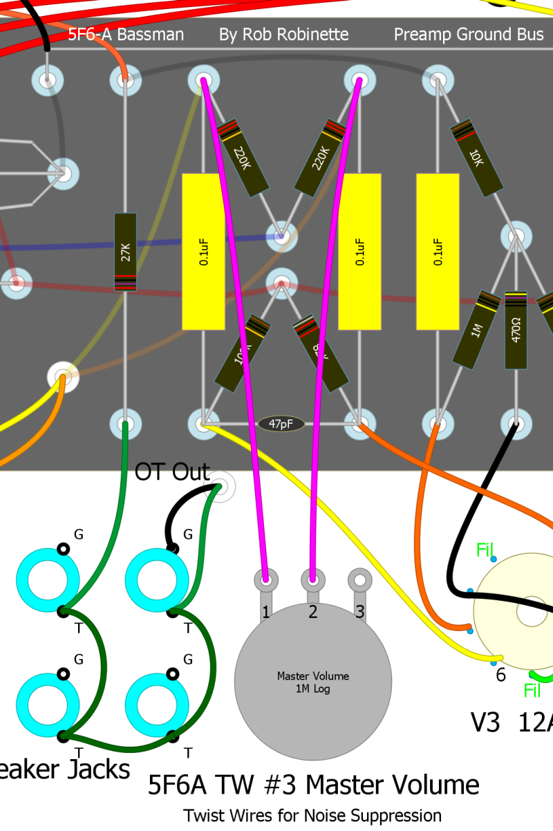
Simple But Effective Trainwreck Type-3 Post Phase Inverter Master Volume (PPIMV)
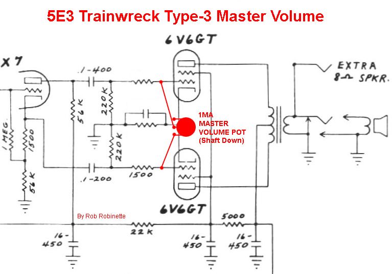
Add a 1 megaohm audio (log) pot and two wires and you've got an effective post phase inverter Master Volume. As you turn the Master Volume pot down (counterclockwise, pot is shown shaft down) more of the opposite phase signals from the phase inverter are mixed together which cancels the signal out. I did this mod to my 5F6A Bassman and it works great.
59 Bassman Reissue Type-3 Master Volume
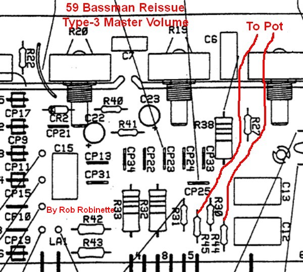
Connect resistors R44 and R45 (power tube grid stopper resistors) to the Master Volume pot.
If you are anal you can completely eliminate the Type-3 from the amp circuit by adding a switch to disconnect the circuit. Use a 250KA pot with a push-pull DPDT switch and wire one leg of the master volume through the switch so when the master volume knob is down the circuit is completely disconnected. Pull the knob up to activate the master volume. A 250KA pot will give you a better volume sweep than a 1MA and since we can disconnect the MV we don't have to worry about the 250KA pot affecting the amp tone.
To do this you would run the wire from the #2 (center) pot terminal to the upper left DPDT switch terminal, then run a wire from the middle left DPDT switch terminal to the circuit board's right 220k resistor. The wire from the #1 (left) pot terminal would be wired as normal to the left 220k resistor (see layout below).
Type-3 With MV ON/OFF Push-Pull Pot
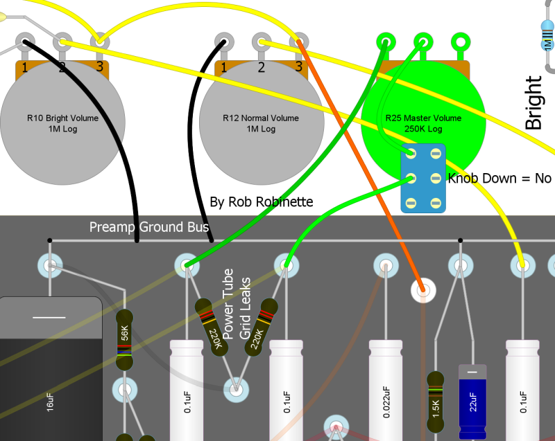
Master Volume knob Down = no master volume at all, Up = master volume on. This diagram shows a 5E3 Deluxe but the push-pull switch wiring is the same.
Another option is to use a switch and resistor for your master volume instead of a pot. You simply replace the master volume pot with a resistor on a switch. One guy used a 5k 1/2 watt resistor which gave him his preferred "bedroom practice" output level. Switch OFF = no master volume at all, ON = bedroom volume.
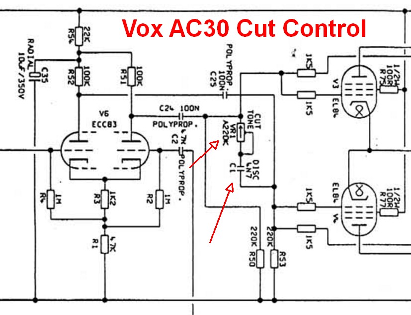
Master Volume + Vox Cut Control
I'm a big fan of the VOX style Cut Control because it's a great way to "trim the ice pick". Early in-the-circuit tone controls affect the substance of the overdrive tone. High freqs generate overdrive harmonics that fill in the top end. If you turn down a normal tone control to reduce ice-pick highs you'll kill all the harmonics too. A cut control allows you to trim off very high ice pick highs without removing all the high frequency overdrive harmonics. All high gain amps should have early and late tone controls for this reason. You can just leave the cut control on full high and you have a normal amp circuit.
The Vox Cut Control connects the two power tube grids with a 220k audio pot and 4.7nF (.0047uF) capacitor to allow variable high end cut. In a push-pull amp the guitar audio signals on the two power tube grids are 180 degrees out of phase with one another so mixing them together nullifies the signal, kind of like mixing matter and antimatter. The capacitor limits the effect to high frequencies but if you jumper around the cap the pot becomes a Trainwreck Type-3 master volume.
I like this very late tone tweak because it pairs well with an early tone control or stack. Use the early tone control to get the overdrive tone and substance you want then use the Cut Control to fine tune the tone. The Cut Control affects only the power tubes.
Wire the cut pot as a variable resistor so that as you turn the knob up (clockwise) resistance increases. Up = more resistance = brighter tone. Connect the Cut Control to the two phase inverter outputs between the coupling caps and grid stopper resistors (see schematic below).
220KA or 250KA pot (audio pot wired as variable resistor) and .0047uF 200v cap connect the two phase inverter outputs between the coupling caps and grid stopper resistors.
Cut Control on 5F6A Bassman
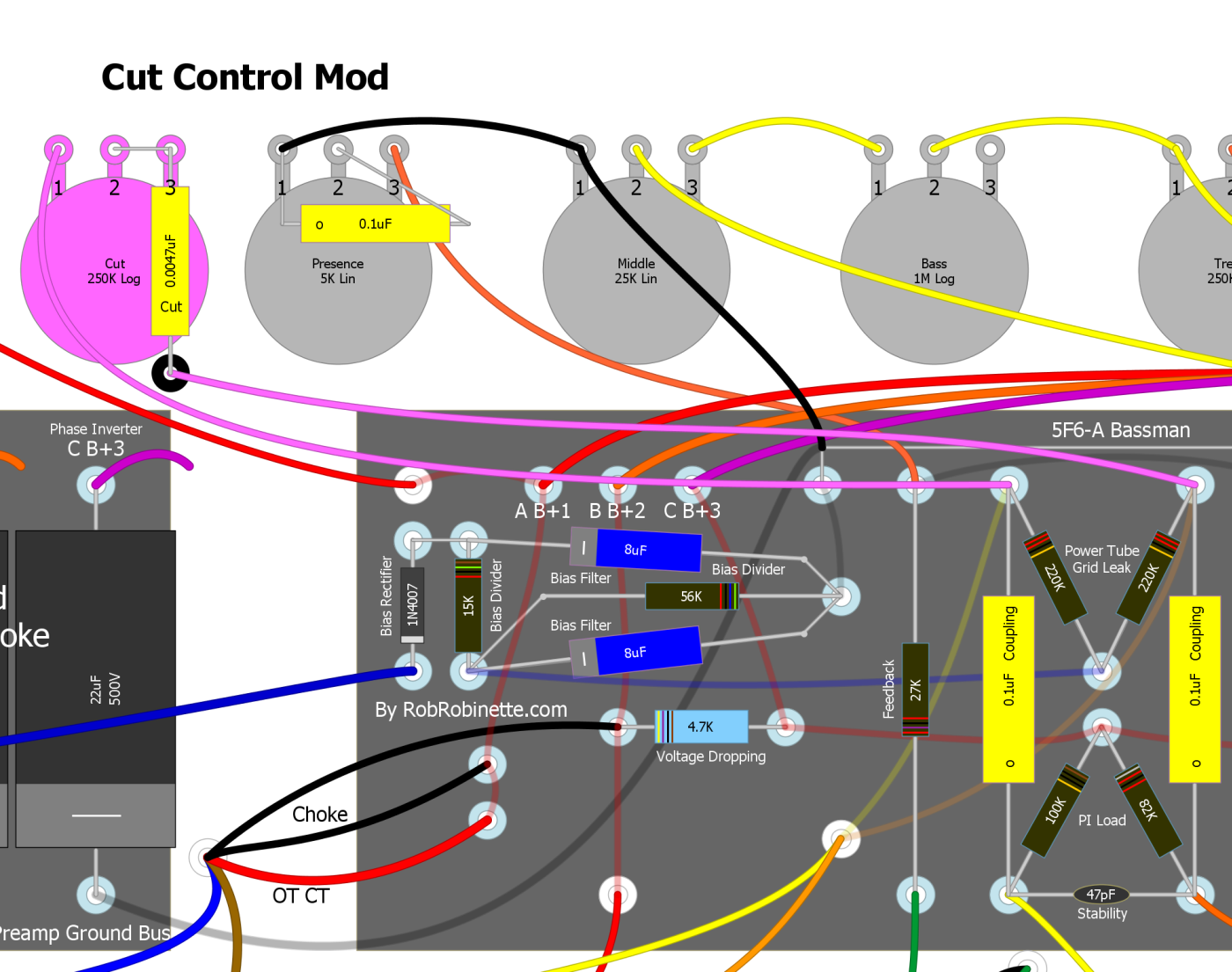
The .0047uF Cut Cap can be supported by a non-grounded terminal strip.
Master Volume + Cut Control Push-Pull Pot Mod
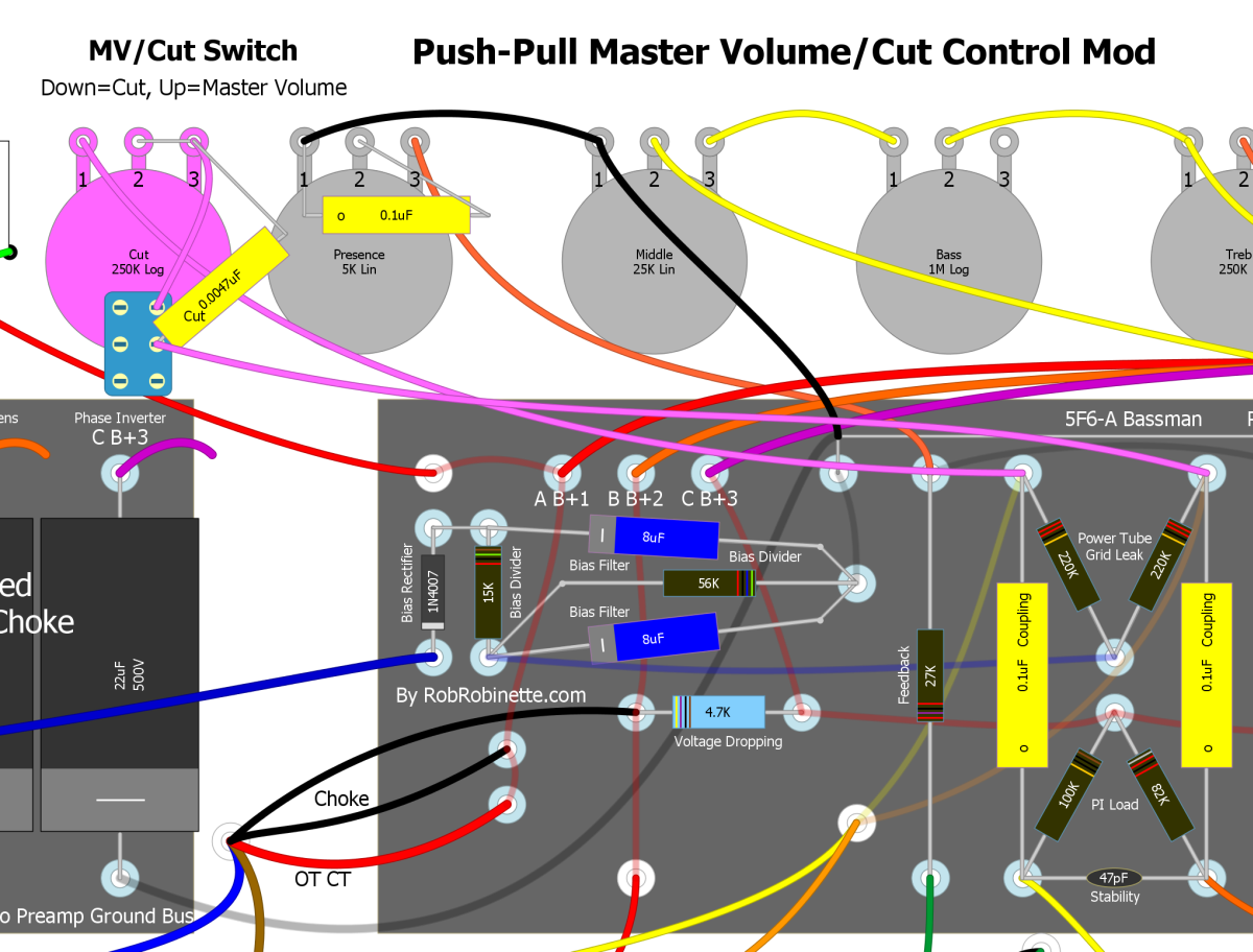
Use a 250KA push-pull pot and you can push the pot down for Cut Control or pull it up for Master Volume. Connect the cut capacitor from pot terminal #3 to the middle switch terminal.
59 Bassman Reissue Type-3 Master Volume/Vox Cut
Connect resistors R44 and R45 (power tube grid stopper resistors) to the Master Volume/Vox Cut pot.
One Wire Cascade Mod
This is how the Old school converted their JTM45 (Marshall Bassman copy) into a high gain rock machine. It's a simple and easily reversible mod that sends the Normal channel output into the Bright channel's input for an extra gain stage. I also suggest changing the Bright channel's 270k mixing resistor to a 470k to help the V2A gain stage handle overdrive from the previous two gain stages. Another option to consider is changing the Normal channel's .02uF coupling cap to a .0047uF (400v or higher) to reduce some bass to tighten up the overdrive tone. The Normal channel coupling cap is the rightmost .02uF cap on the layout below. The Normal Volume control will function as a first stage "gain" control and the Bright Volume will function as the second stage volume.
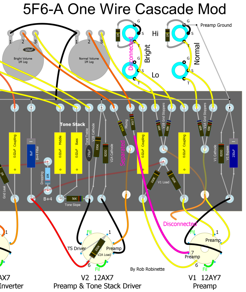
1. Disconnect the wire on V1 pin 7. 2. Disconnect the bottom of the Normal channel 270k mixing resistor. 3. Run a jumper wire from the output of the Normal Channel's 270k mixing resistor to V1 pin 7. 4. Optionally replace the Bright channel's 270k mixing resistor with a 470k 1/2 watt resistor. The new resistor will function as the V2A preamp's grid stopper and help control the heavy overdrive caused by the cascade mod. Another option to consider is to replace the Normal channel .02uF coupling cap with a smaller .0047uF (400v or higher) cap to reduce some bass frequencies to tighten up the overdrive tone.
Add an FX Loop
A simple passive effects loop is as simple as adding two jacks and a little wire. The preferred location for adding an FX loop is between the volume pot wiper and the following phase inverter coupling cap. If you choose to go with an active FX loop I would still put it in the same place. This mod works for the Marhsall JTM45 also. If installing it in a Marshall amp with a pre-phase inverter master volume I would move the FX loop to directly after the Master Volume output.
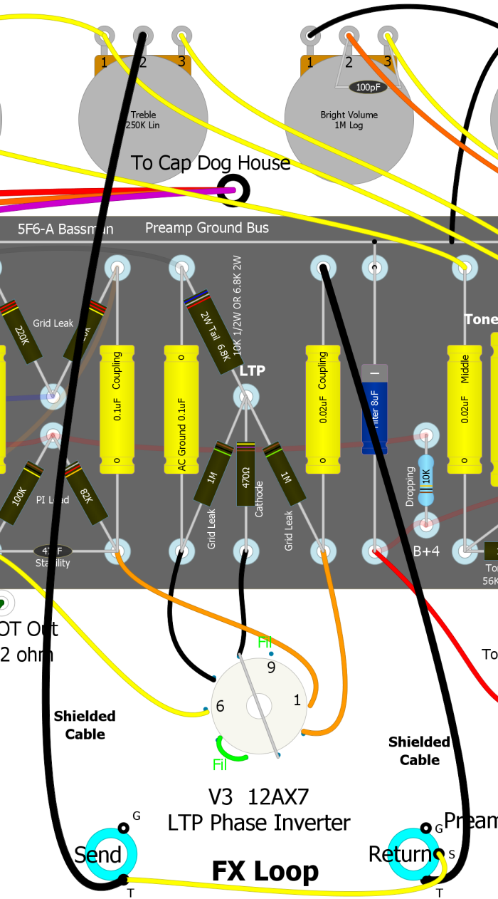
5F6A Bassman or JTM45 passive FX loop shown. Insert a passive or active FX loop between the treble pot wiper and the 0.02uF phase inverter coupling cap. Placing it here uses the cathode follower to minimize interaction between FX and the amp. I recommend RG174 shielded cable for the runs to and from the jacks. Ground the cable shield at one end only at the Send and Return jacks ground terminals. The Send jack is a Switchcraft 11 jack. The Return jack is a Switchcraft 12A (switched). Both jacks are grounded to the chassis.
Preamp Local Negative Feedback
This mod is an extremely easy to add local negative feedback loop that can be used to tune the overdrive tone of any high gain preamp. If you do a cascade mod like the previous "One Wire" mod this little mod is worth a try. The feedback is negative because the plate is 180 degrees out of phase with the grid. The mod connects a preamp's second or third gain stage plate back to its grid through a 22M to 44M resistor and .047uF (400v or higher) cap.
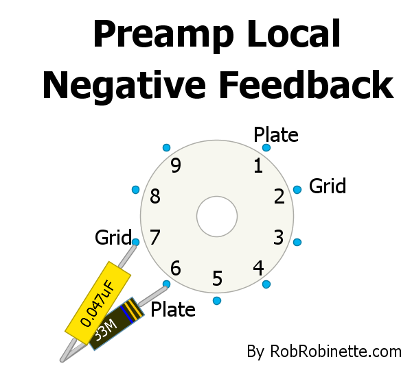
A 22M to 44M resistor and .047uF 400v+ cap connect the preamp grid and plate together to form a local negative feedback loop.
The mod can also be used on the "A" triode pins 1 and 2.Like most amplifier negative feedback loops this mod will reduce distortion, tighten the transition from clean to dirt and slightly reduce gain. At first blush I was going to recommend not using this mod on the first stage of amplification because if the cap fails as a short it could inject high voltage into the guitar circuitry but even if this does happen the large value feedback resistor will limit the current to 18 micro amps (.018 milliamp) or less so it's not a concern. This mod would be of relatively little use in the first gain stage anyway since it is rarely overdriven.
If this NFB loop tightens up the tone too much try a larger value resistor like a 44M. The larger the resistor the less negative feedback gets through to the grid. This is a pretty cool yet extremely simple circuit that should be experimented with in all high gain preamps.
3-Way Preamp Bias Switch
The normal value for a preamp cathode resistor is 1.5k which will typically give you symmetric clipping when it is overdriven. The Bassman's V2A second preamp stage uses a hot 820 ohm non-bypassed resistor which will gives hot asymmetric clipping. Many Marshall preamps use a cool 2.7k cathode resistor which leads to cool asymmetric clipping. This 3-Way Preamp Bias Switch will let you select Hot - Cool - Normal bias. In the diagrams below the switch is connected to the V2A cathode (pin 3) but this switch could also be used on V1A (pin 3) or V1B (pin 8) if you remove the jumper between V1's cathode pins (3 and 8) to separate the two cathodes. There is an overdrive tonal difference between all three switch positions.
The switch is a SPDT (single post dual throw) ON-OFF-ON mini switch with the cathode connected to the center switch terminal and the far end of the resistors grounded.
3-Way Preamp Bias Switch Without Bypass Caps
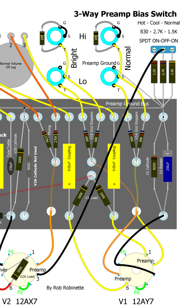
The Bassman's V2A cathode resistor is switchable for Hot (830 ohms) - Cool (2.7k) - Normal (1.5k). Note the original 820 ohm resistor on the circuit board is no longer used (shown grayed out). When the switch is in the left position the 2.7k and 1.2k resistors are paralleled for 830 ohms. In the middle position only the 2.7k resistor is used. In the right position the 2.7k and 3.3k are paralleled for 1.5k.
3-Way Preamp Bias Switch With Always On 25uF Bypass Cap
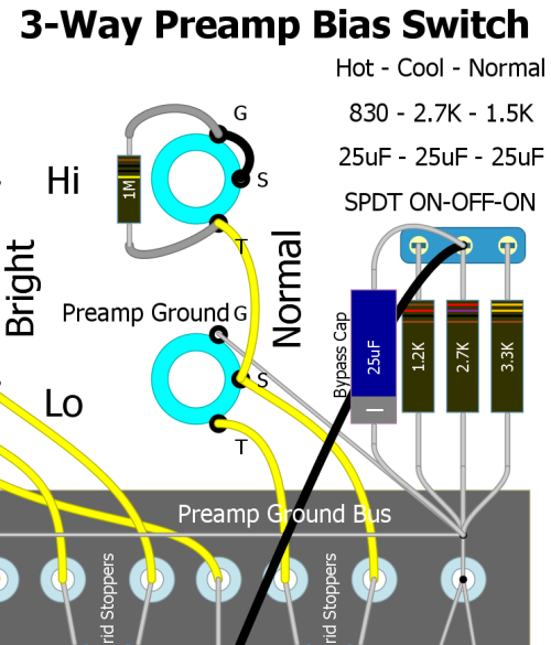
With a 25uF 25v bypass cap across the center 2.7k resistor the cathode is bypassed in all 3 positions. The bypass cap value is your choice and can range from 250uF (5F6A V1) to .68uF (Marshall high gain). Many Fender tweed and blackface amps used a 25uF bypass cap on the first preamp stage.
3-Way Preamp Bias Switch With Switchable Bypass Cap
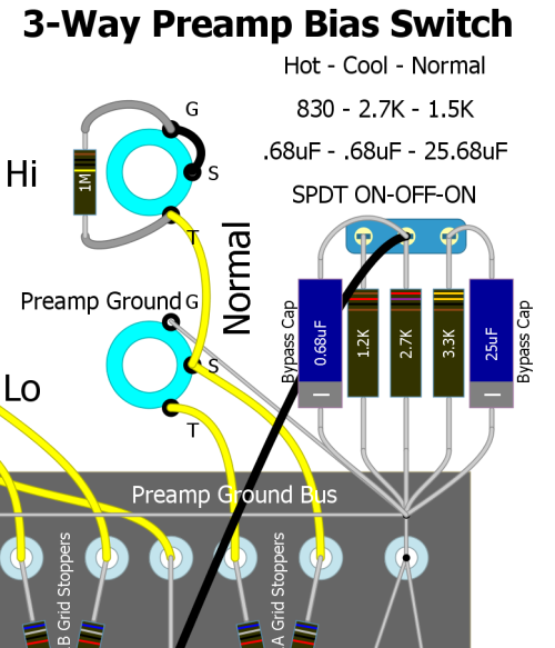
With a .68uF 25v bypass cap across the center 2.7k resistor and a 25uF 25v cap across the 3.3k resistor the cathode is bypassed at .68uF in the Hot and Cool positions and 25.68uF in the Normal position. High gain amps often use a hot or cool biased triode bypassed at .68uF. Fender tweed amps typically use a 1.5k bypass resistor and 25uF bypass cap.
Channel Jumper Switch
Since channel jumpering is so common among Fender players this mod will let you leave your jumper cable at home and jumper the Bright and Normal channels with the pull of the Normal volume knob. You can plug your guitar into any jack and you will get a Hi jack-to-Hi jack jumper.
Just swap out the Normal Channel volume pot for a 1MA Push-Pull pot with DPDT switch (Bourns Model PDB183-GTR). If you prefer you can use a separate ON-ON DPDT switch to do the same thing. This switch will work on any amp that has Fender style four inputs (Bright/Normal/Hi/Lo).
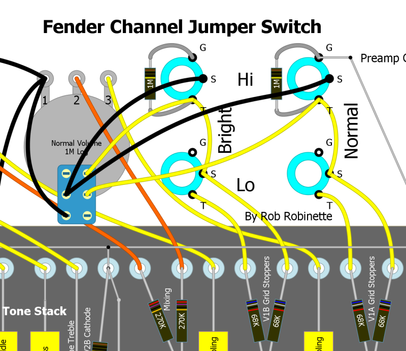
Note the wires between both Hi Jacks' ground and switch terminals have been cut.
With the Normal volume knob down the input jacks function normally with the jacks grounded when nothing is plugged in. Pull the Normal volume knob up and the two Hi jacks are jumpered together for a fatter tone. Your guitar signal will flow through both V1A and V1B preamp tubes in parallel which adds some texture and complexity to the tone. For more info on channel jumpering see this.
To install the switch first remove or cut both Hi jacks' wire that runs between their tip and switch terminals. Then remove the Normal volume pot and wire the three volume pot terminals normally. Wire the DPDT switch part of the pot as in the layout above and you're done.
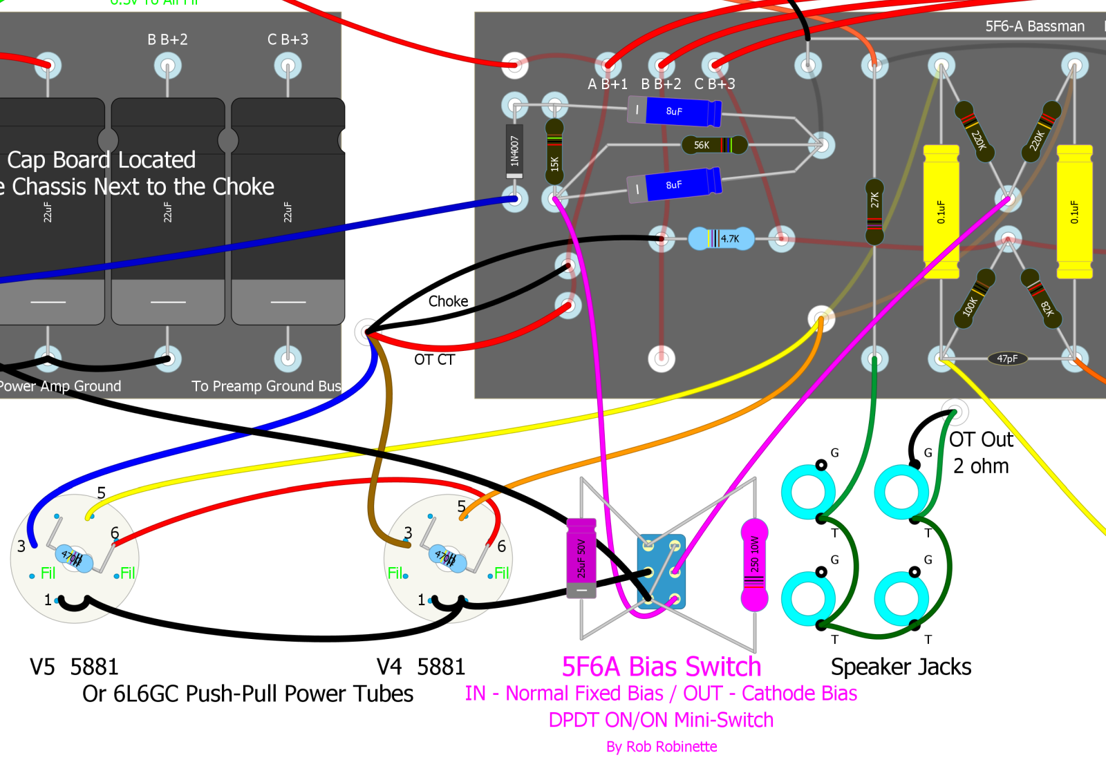
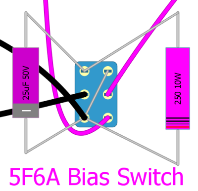
Fixed / Cathode Bias Switch
The 5F6A uses a fixed bias circuit to bias the power tubes. You can install a 2-way toggle switch on the 5F6A to flip between normal fixed and cathode bias.
With this bias switch it's like having two different amps. You can run the amp in standard fixed bias mode or flip the switch to a more 5E5 Pro vibe with a more 'tubey', round, warm and compressed tone due to it's fluctuating cathode bias. Fixed bias tends to sound cleaner and punchier, especially the lows and it develops more power than cathode bias. There is a 'pop' when switching modes but it's not too loud and won't hurt anything.
The Fender 5E5 Pro used 6L6 tubes and a 250 ohm 10 watt cathode resistor so I recommend the same. The Pro came with a 25µF 25 volt cathode bypass capacitor which simply parallels the 250 ohm cathode resistor to boost gain. I recommend a 25µF 50 volt cap (rather than the Pro's 25 volt) because the voltage drop across the cathode resistor can easily exceed 25 volts.
The toughest part of this mod is lifting the circuit board to remove the wire that carries the bias voltage from the bottom of the bias circuit to the two 220k power tube grid leak resistors. You have to replace that bias wire with the two wires running to the switch shown below. If you haven't built your 5F6A yet consider running the bias supply wire above the circuit board for access for future mods.
You can avoid removing the old under board bias wire by disconnecting both 220k power tube grid stopper resistors from their shared lower turret. Then use insulated 20 to 24 gauge solid core wire (solid so it will stay in place) to run from the bias switch to the disconnected resistor turret. Put two wire wraps around the turret. The wire insulation needs to be on the wire for the turret wrap to keep the wire isolated from the turret. Then solder the resistors to the end of the wire. Make sure the resistor leads do not make contact with the turret. You could also disconnect the 15k and 56k bias resistors and 8uF capacitor from their shared eyelet or turret to isolate them from the under-board wire.
5F6A Bias Switch
Remove Old Bias Wire
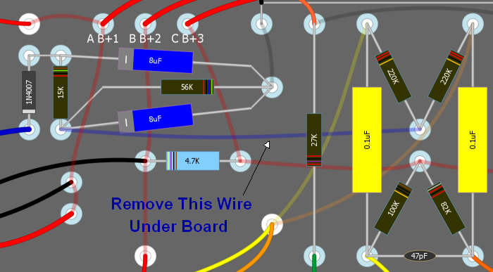
The wire is usually located below the circuit board.
Switch Detail
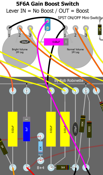
Gain Boost Switch
Add a switched 0.68uF (25v or higher) bypass cap to V2A's 820 ohm cathode resistor to boost preamp gain. The added preamp gain allows for earlier breakup and more overdrive. The bypass cap will also modify the overdrive behavior of this triode and all the downstream tubes so this mod does more than add gain, it fundamentally alters the nature of the amp's overdrive tone.
In the JTM45 Marshall installed a higher gain 12AX7 in V1 to boost preamp gain but this mod adds a similar amount of gain at the flip of a switch. I like to use this gain boost in conjunction with the Negative Feedback Switch in the JTM45 position. The higher gain from the boost switch compliments the extra feedback.
I placed the SPST ON/OFF mini-switch on the front panel between the two volume pots. I mounted the bypass capacitor between the switch and the Normal Volume pot's ground.
Another option is to add a 50KL pot between the bypass cap and ground so you can vary the amount of bypass boost with the pot.
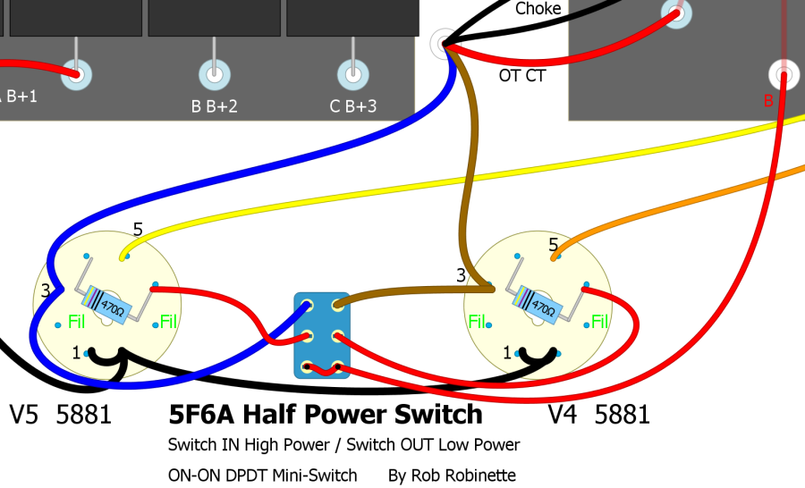
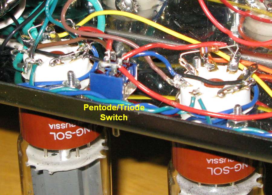
Pentode / Triode Half Power Switch
This is a simple mod that allows you to cut your output power almost in half. I installed a DPDT (Dual Post Dual Throw) ON/ON mini-switch between the power tube sockets so the wire runs are very short. When the switch lever is pushed inward the power tubes are in normal, high power pentode mode. Pull the switch lever out and the screen grids are connected to the plates putting the tubes in low power "triode" mode. The amp's clean and overdrive tones are a little different in triode mode so this mod opens the amp's tonal pallet.
Half Power Switch in the BootHillAmps.com SixShooter
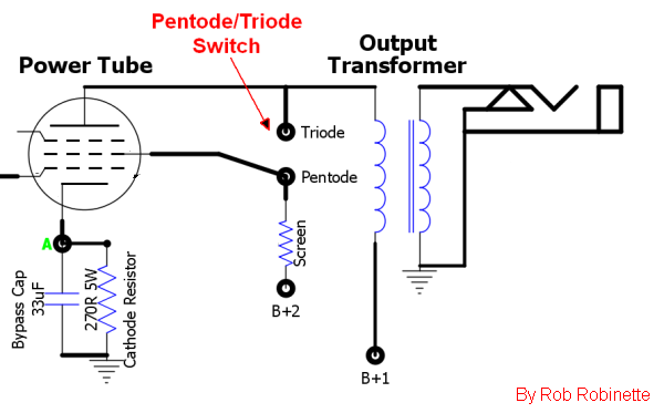
Power tube screen grid is connected to either the plate in the triode mode, or the B+2 screen power supply in the pentode mode.
The switch ties the power tubes' screens to the plates which eliminates the screens' function creating a virtual triode which cuts the tubes' output power almost in half. The 5F6A circuit is unaltered in the High Power mode. The black jumpers connecting tube pins 1 and 8 are EL34 tube compatibility jumpers.
EL34 Power Tube Compatibility Jumper
Using EL34, KT66, KT77 and KT88 power tubes will give your 5F6A more of a "British" or "Marshall" tone. The EL34 is a true pentode while the rest of the tubes listed are beam tetrodes. True pentode tubes offer up more screen current when overdriven so they typically generate more power tube distortion. EL34's also need less input signal for maximum output so they tend to shift the balance of preamp to power amp distortion toward the power amp.
You need three conditions to safely run EL34 power tubes hard in a 5F6A Bassman:
The power transformer must put out enough 6.3v heater current to satisfy the EL34's appetite for 1.6 amps per tube. The 5F6A's preamp tubes use .3 amps per tube so your power transformer must be rated for at least 4 amps of 6.3v current. Many are only rated for 3 amps.
You will also need to install a jumper from pins 1 to 8 on both power tube sockets. This will tie the EL34's suppressor grid to the cathode. The 6V6, 6L6 and KTxx tubes have internal jumpers that do this. Adding the jumper will not affect 6V6, 6L6 or other tubes. The original Fender 5F6A layout shows these jumpers in place.
Since the EL34 is a true pentode (not a beam tetrode like the 6V6, 5881 and 6L6) their screen grid picks up and flows more screen current so many EL34 amps use 1k 5 watt screen resistors instead of the 5F6A's 470 ohm 1 watt which is mounted directly on the power tube socket. I left mine at 470 ohms but increased them to 5 watts because increasing its ohm value will change the amp's clean and overdrive tone by altering the overdrive screen grid voltage drop. For more information on screen grid voltage and overdrive tone see Tube Guitar Amplifier Overdrive. If you are going to push the amp hard with EL34's on a regular basis I recommend upgrading the screen resistors to 470 ohms and 5 watts. Splitting the difference by using 750 ohm 5 watt screen resistors is also an option that should be considered if you plan to run 6L6 and EL34s.
Jumper Pins 1 & 8 together. The jumper does not affect 6L6 or 6V6 or any other tubes.
My 5F6A Head with JJ KT88 Power Tubes
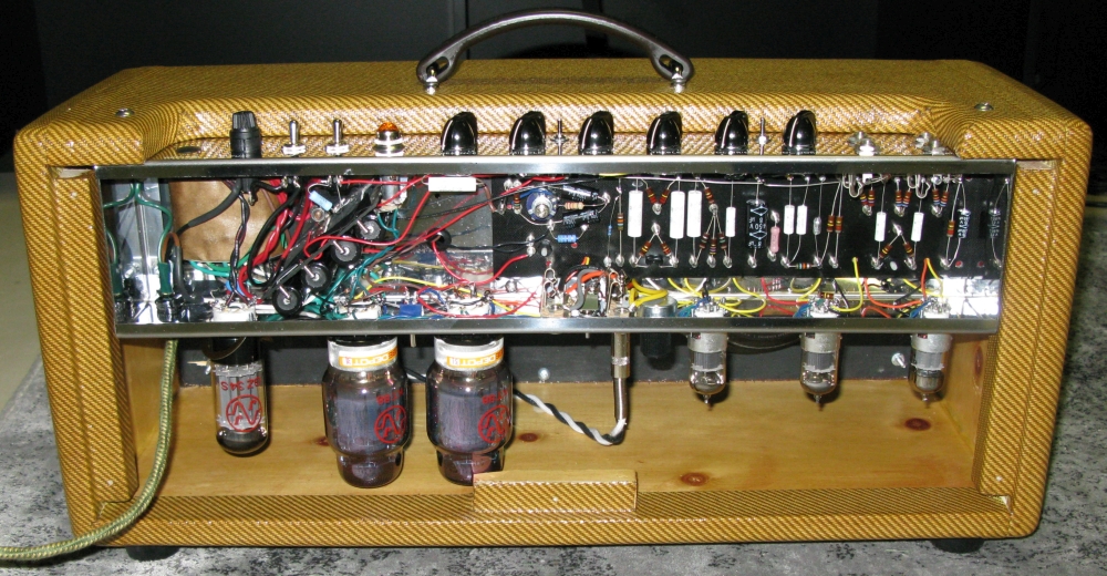
My 5F6A head amp can use 6V6, 6L6, EL34, KT66, KT77 and KT88 power tubes. I ordered my head cab with about one extra inch in height to fit the taller KT88 tubes.
KT88's like more plate voltage than the 5881 and 6L6 so plugging in a solid state rectifier into the rectifier tube socket will raise the plate voltage by about 10 to 20 volts and put the big tubes closer to their sweet spot. One downside to doing this is it will also raise the voltage on the phase inverter and preamp tubes and the V2B cathode follower is already stressed by the stock voltage.
In my 5F6A the KT88's biased at -45.5 on the grid, 430 on the plates and 55 milliamps of plate current for 68.7% of their rated 35 watts of plate dissipation. That's with a JJ GZ34S rectifier tube. My primary Tung-Sol 5881's biased at -45.1 grid, 443 plate, 40.7ma for 69.3% of their rated 26 watts.
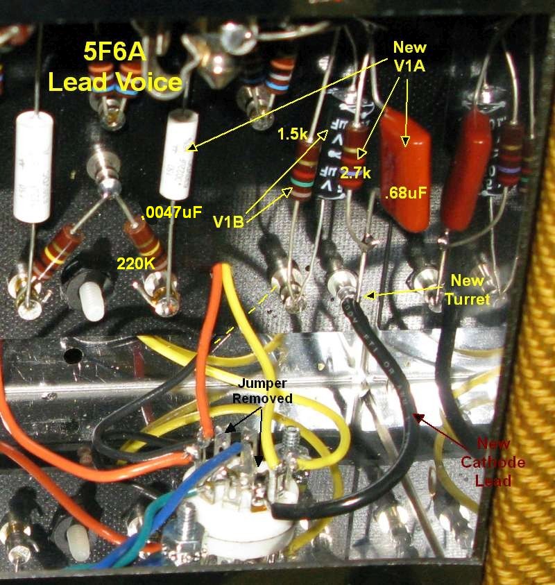
Voice a "Lead" Channel
This is another one of my favorite mods. It's possible to voice one of the 5F6A's channels with a more modern, tight, Marshall "Lead" style tone. Remember, the only difference between the 5F6A Normal and Bright channels is the bright cap on the bright volume pot which bypasses high freqs around the volume pot at low volume levels. At max volume there is no difference between the Normal and Bright channels so voicing one channel differently is a useful mod.
This mod will tighten up the overdrive tone and bottom end and make your 5F6A more pedal friendly. Modifying only the first gain stage removes some of the guitar's low frequencies so the clean tone will be thinner but during overdrive later gain stages with larger coupling caps will allow low frequency intermodulation distortion harmonics to be passed through the amp for a subtle but thick low end. This will not happen in an amp with small coupling caps throughout. This "Lead" Channel mod will blow away your Marshall buddies.
You will also gain some clean headroom and maximum volume because low frequencies use up a lot of the amps power so removing very low frequencies allows more amplification of the remaining audio frequencies.
When evaluating this mod be sure and try a boost pedal to get the gain and distortion up--this is when this mod really shines.
Here's an excellent demo showing the difference between the 5E3 unmodified Bright channel and the "Lead Channel:" kdj 5E3 Lead Channel YouTube Demo
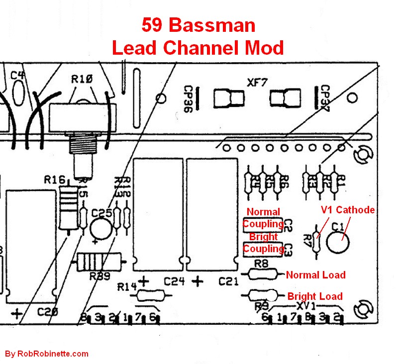
I used the Marshall 1987 Plexi as my roadmap for this "Lead" channel mod. The Plexi uses preamp component values to reduce low frequencies and boost high frequencies to offer a clean, tight, modern overdrive tone. The Lead channel will also be more pedal friendly than a normal 5F6A channel. This modification separates the V1 cathodes, increases the "Lead" channel's load resistor, cathode resistor, reduces its bypass capacitor and reduces the coupling capacitor. The unmodified channel gets a new 1.5k cathode resistor that's equivalent to the shared 820 ohm resistor. The original 250uF bypass capacitor is reused (yes, that's 250uF not 25).
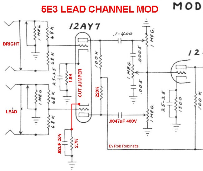
Schematic of the Lead Channel mod on the 5E3 Deluxe. The mod is exactly the same in the 5F6A.
The first step for this mod is to separate V1's cathodes so we can use different value bypass capacitors on each channel. We must also remove the cathode jumper from pins 3 to 8 on the V1 tube socket. The "Lead" channel gets a much smaller, Marshall size 0.68uF (50v or higher voltage) bypass capacitor to attenuate lower frequencies which will clean up and tighten the overdrive tone. This size bypass capacitor is rare but it does not need to be an electrolytic. The unmodified channel uses the original, huge 250uF 25v cap so its tone will not change. The 250uF cap is large enough to boost the gain of all frequencies, including very low bass guitar frequencies. You can modify either the Normal or Bright channel but I modified the Normal channel because I mostly use the Bright channel. I left the Bright channel as Leo Fender designed so I can still get the standard magical 5F6A tone when I need it.
If you choose to modify the bright channel into the lead channel I recommend you remove the bright cap to keep the overdrive tone from getting too spikey.
Note that when we separate the cathode resistors we have to double their value to retain the same bias so V1 pin 8 (my unmodified channel) needs a 1.5K 1/2 watt cathode resistor (original was 820 ohms) to keep the same bias and tone. For the "Lead" channel (V1 pin 3) we move up to a 2.7k cathode resistor to cool the bias for Marshall style asymmetric clipping distortion. V1A's bias point is shifted toward cutoff so the guitar signal's negative lobe will get clipped at cutoff with a lower level input signal leading to earlier distortion onset. Negative lobe cutoff clipping will also occur earlier than the positive lobe (which gets clipped much later by saturation). With this asymmetric clipping the positive lobe carries the undistorted musical content while the negative lobe carries the distortion. Asymmetric distortion also adds even order harmonics and shifts the audio wave duty cycle away from 50% and makes the distortion sound more tubey and distinct from solid state distortion. Asymmetric distortion is often described as sounding "creamier" with less fizz than symmetric distortion.
Increasing the V1A load resistor from 100k to 220k will increase the channel's gain and make distortion in the V2A preamp more likely. I recommend using a 1 watt resistor to reduce resistor hiss.
We also want to reduce the value of the "Lead" channel coupling cap from 0.022uF to 0.0047uF (400v or higher) to again suppress unwanted bass frequencies but more importantly reduce bias excursion recovery time and therefore reduce preamp blocking distortion in the second preamp stage which will also smooth and sweeten the overdrive tone. Note that 0.0047uF = 4.7nF (nano Farad). If you don't want to deal with splitting the V1 cathodes just installing the 0.0047uF coupling cap will go a long ways toward tightening up the tone of just about any tweed amp channel.
If you don't want to go to the trouble of adding an eyelet or turret for the extra cathode resistor and bypass cap you can simply glue the capacitor to the circuit board and solder the cathode resistor lead and cathode wire to the cap's lead. The glued down cap will provide enough support for the resistor and wire.
V1's extra caps and resistors can get a little crowded on the circuit board so it's a good idea to raise the hot cathode resistors higher off the circuit board than the coupling caps to aid cooling and minimize heat transfer from the resistors to the caps.
This mod works great with a higher gain 12AX7 in V1 (like the Marshall JTM45) and/or with the Gain Boost Switch mod and Switched Negative Feedback. My 5F6A sounds amazing when using the Lead channel with the Gain Boost Switch on and negative feedback set to the JTM45 position.
Lead Channel Mod
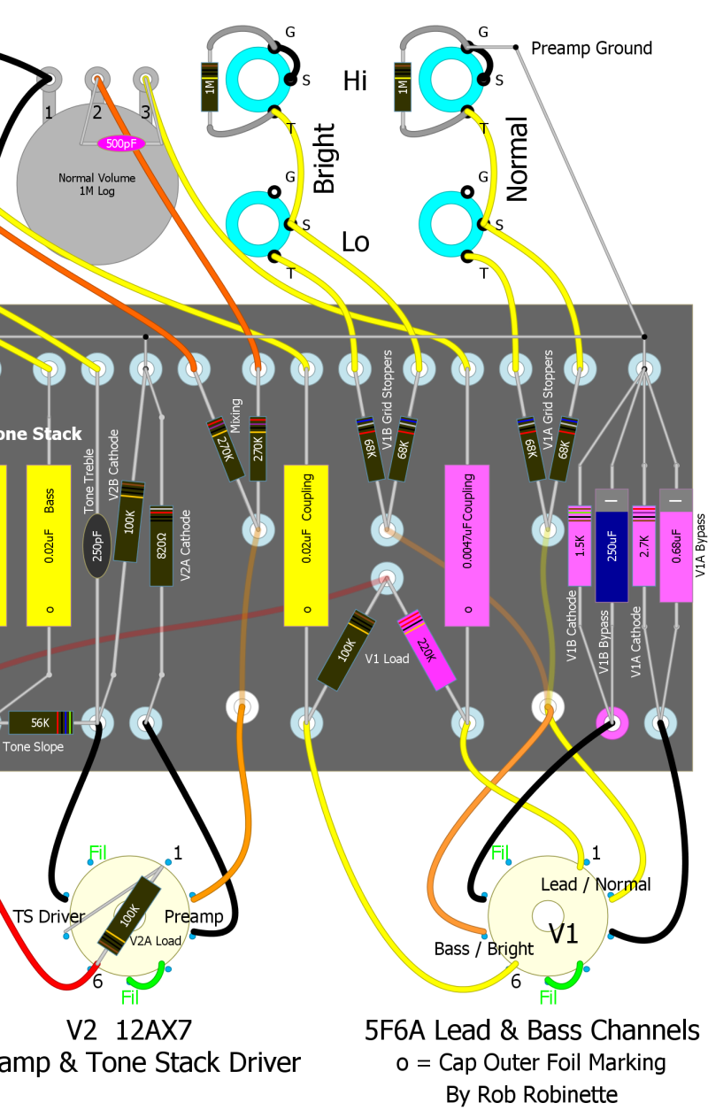
Modified components shown in pink. V1's cathodes are separated using two cathode resistors and two bypass caps. Don't forget to remove the cathode jumper between socket pins 3 and 8. The "Lead" channel gets a 220k 1 watt load resistor, 2.7k 1/2 watt cathode resistor, 0.68uF 25v bypass cap and a 0.0047uF 400v coupling cap. The unmodified channel needs a 1.5k 1/2 watt cathode resistor since only one cathode is drawing current through it. I also added a 500pF bright cap to the Normal volume pot to match the Marshall Plexi Lead channel.
Run 6V6 Power Tubes
Pairing the Bassman's preamp and long tail pair phase inverter with 6V6 power tubes will give you small bottle tone but lots more power tube overdrive because the LTP's output can fully overdrive the little 6V6 power tubes.
But to get the most out of a 6L6 it needs higher B+ voltage than a 6V6 and more current output from the power transformer. But if you build the amp with a bigger 6L6 power tranny then the 6V6 loses a lot of voltage sag so it sounds stiffer and punchier with a noticeably tighter low end (sounds more solid state and less tubey). This effect can be overcome in the 5F6A by using a 5Y3 rectifier tube which will still cause voltage sag with 6V6 tubes.
Same problem with the output transformer. The 6L6 needs a higher current rating tranny than a 6V6 so it won't just saturate at 6V6 levels (more 6L6 output current = more saturation and compression with no more volume). But then a 6V6 using a bigger tranny loses it's compression and sounds more dynamic and solid state.
If the amp has a multi-tap output transformer (and all amps designed to run 6V6 and 6L6 should have them) most of the output tranny impedance mismatch can be handled by using a one step higher speaker impedance setting -- if the amp is designed for 6L6 then set the impedance selector to 8 ohms with a 16 ohm speaker or set to 4 ohms with an 8 ohm speaker.
You also need to lower the amp's B+ voltage so you don't burn up the 6V6 tubes. You can do this by simply installing a 5Y3 rectifier tube.
You may also need to adjust the bias after installing the 6V6 tubes. If your bias is not adjustable it will probably be OK with 6V6's but watch the power tubes for red plating at first power up and measure the bias to see where they are running.
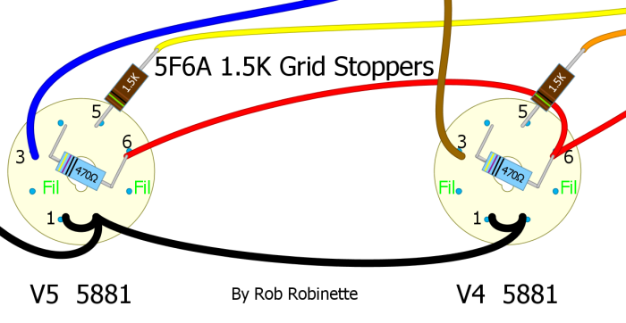
Add Power Tube Grid Stopper Resistors
The 5F6A design is pushed to the edge of stability and Fender even had to add a stability capacitor across the phase inverter output to keep the design from oscillating too easily. When pushed hard the amp can still oscillate and the addition of two 1.5k or 5.6k 1/2 watt power tube grid stopper resistors can help stabilize the power amp circuit. The follow-on black face AB165 and silver face AA375 Bassman came with 1.5k 1/2 watt grid stoppers. Even the 5E3 Deluxe came with 1.5k grid stoppers (but did not have screen resistors). Almost all modern amps have power tube grid stopper resistors. Grid stoppers can help prevent blocking distortion and protect your power tubes from damage when driven hard into overdrive when grid current begins to flow.
The chance of oscillation is reduced by removing frequencies beyond human hearing when the grid stopper resistance combines with the tube's Miller capacitance to form a low pass RC (resistance/capacitance) filter.
To maximize a grid stopper's effectiveness it should to be mounted directly to the tube's grid pin. Just remove the wire from each power tube socket's pin 5 (grid) and solder a resistor directly to the grid pin and solder the wire to the other end of the resistor. You can bend the resistor's lead into a small loop to make attaching the wire easier.
If your Bassman doesn't oscillate--ever, then I don't recommend adding grid stopper resistors because it will change the overdrive tone and the 5F6A's overdrive tone is freakin' perfect. The overdrive tone is changed by making positive lobe grid clipping harder and more abrupt which will sound more "modern and aggressive." A grid stopper will also alter the bias voltage shift and recovery times which affects the character of negative lobe clipping. If you want a '59 Bassman tone you don't want to add grid stoppers. If you want a more modern overdrive tone give them a try. For more information see Tube Guitar Amp Overdrive.
Reduce Ice Pick Highs
If your particular speakers are giving you too many 'ice pick' highs simply adding a 100pF Mica capacitor across the feedback resistor will filter out some very high freqs that can cause ice pick highs. The cap allows high freqs to go around the feedback resistor so they are used for feedback which will reduce them from the amp's output. This is a nice, subtle mod that won't screw up your Baseman's perfect tone. It's easy to use alligator clips to clip the cap in place temporarily to see if you like the mod. If you would like to cut even more highs than the 100pF cap, you can go all the way up to a .022uF cap to lower the filter's cutoff freq so more mid-high freqs would be cut. There's a small chance the Ice Pick Cap can induce oscillation at high volume. If that happens you can put a 4.7k resistor in series with the cap to reduce the very high frequencies that cause oscillation.
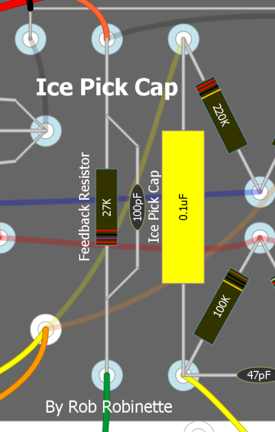
R27 is the NFB resistor.
Add a Simple Line Out Jack
This, along with a headphone jack, is a common mod request. Line outs work well for feeding effects boxes but don't work that great for recording or amplification because an amp's guitar speaker does a lot of tone shaping, high frequency de-emphasis and adds speaker breakup distortion.
tdpri member mungus comments: The raw amp output sounds like crap until its passed through a guitar speaker to tone down the excessive high end - hence the need for some kind of cab simulator.
That's why using a microphone in front of the guitar amp's speaker is the most common way to feed a PA system. If you do go the microphone route use a high quality instrument microphone placed 1/2 to 1 inch from the grill cloth and about halfway between the center and edge of the speaker cone for best tone.
With the cautions out of the way here is a very simple Line Out that does capture the tone and distortion of the entire amp except for the speaker.
5F6A Line Out Jack
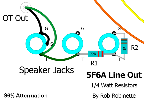
The resistors form a voltage divider and cut the speaker signal by 96%. In this layout the Switchcraft output jacks are self grounded to the chassis. If your output jacks are insulated then the Line Out's ground terminal will need to be connected to ground. The jack can be full size 1/4" or 1/8" (3.5mm) mp3 player size.
Of course the amp's output volume control will control the Line Out volume too--which brings up an important point:
WARNING: A speaker must be attached to the amp's speaker jack when using the Line Out jack to prevent output transformer damage. This tiny little circuit cannot load the transformer properly to run speakerless.
You can replace the 22k resistor with a 250k reverse audio pot (wired as a variable resistor) as a line out level (volume) control. I recommend you also add a 5k resistor between the pot and either jack to set the max volume level. Run the level at minimum volume when not using the line out.
If you are cramped for space for an additional jack you can use your amp's 'extra' speaker jack or even add a small 3.5mm (mp3 player size) jack to save room. To convert the extra speaker jack replace the tip-to-tip green wire with the 22K resistor and add the 1K resistor to the jack's tip and ground terminals.
If you install the Line Out jack near the speaker jack you can use the 22K resistor itself to make the connection from the speaker jack tip terminal to the Line Out tip terminal. Then run the 1K resistor from the Line Out jack tip terminal to your Line Out jack ground terminal. If you use metal Switchcraft style jacks that ground themselves use a star washer against the inside of the chassis to ensure a good Line Out jack ground. If your Line Out jack is insulated from the chassis then you must connect the Line Out jack's ground terminal to a suitable ground point.
The formula to calculate the % of attenuation is:
% Attenuation = 1 - R2 / (R2 + R1) * 100
% Attenuation = 1 - 1 / (1 + 22) * 100 = 96%
Simulate Tube Rectifier Voltage Drop and Sag Using a Solid State Rectifier and Sag Resistor
Voltage drop is the amp's no signal voltage drop caused by the rectifier. A solid state rectifier will only drop about 1.4 volts per diode used so its drop is usually 3 to 6 volts. A tube rectifier will drop more voltage than a solid state rectifier. A GZ34 will drop 10 to 15 volts more than solid state and the 5Y3 will drop around 60v more than solid state.
Voltage sag is the dynamic voltage drop that varies with current demand and causes compression of loud and quiet notes.
If your amp has a solid state rectifier we can simulate tube style voltage drop and sag by adding a sag resistor to the rectifier's output. To determine the value and watt rating of the sag resistor we need to know what type of tube rectifier we're trying to emulate (how much voltage drop do we want) and how much B+ current will flow through the resistor. We already know the 5F6A pulls about 113 milliamps of B+ current so we have that value. If you want to do this for another amplifier you can get a good estimation of B+ current with this online calculator.
Here's a chart from 300guitars.com showing different rectifier voltage drops:
So if we want to simulate a 5V4 we need to drop about 25 volts.
The equation to determine the amount of resistance in ohms to drop a voltage is:
Resistance = Volts / Amps = 25 volt drop / .167 amps = 149 ohms
We can round to the standard resistor size of 150 ohms.
The equation to determine power in watts is: Watts = Volts * Amps = 25 volt drop * .167 milliamps = 4.175 watts
We need to approximately double the watts to cover ripple currant and add long term reliability so I would use a 150 ohm 10 watt sag resistor to simulate a 5V4 tube rectifier in a 5F6A with a solid state rectifier. The sag resistor would go between the solid state rectifier's output and first filter capacitor.
Lower the B+1 Voltage
Modern wall voltages are higher than they were back in the 50's when Fender tweed amps were designed so today's wall voltages can increase your B+ by over 30 volts. Lowering your amp's B+ voltage can lengthen tube life and soften its tone. You can do this with a rectifier tube swap. Here's a chart from 300guitars.com showing the different voltage drops:
My Rectifier Tube Comparison
| Solid State | JJ GZ34S | GT 5U4 | JJ 5U4GB | |
| AC in to Rectifier | 682v AC | 678 | 677 | 677 |
| B+ | 434v DC | 416 | 392 | 384 |
| Drop from Solid State | - | 18v | 42 | 50 |
| V2B Plate | 252v DC | 238 | 226 | 221 |
| V2A Plate | 206v DC | 195 | 185 | 181 |
| V1B Plate | 207v DC | 197 | 188 | 184 |
| V1A Plate | 201v DC | 190 | 182 | 177 |
| Power Tube Plate to Cathode V | 403v DC | 379 | 360 | 351 |
| Cathode Voltage Drop | 32.2v | 30.3 | 28.6 | 27.7 |
| 6L6GC Cathode Bias Output @ 4ohms | 17.9 watts | 15.5 watts | ||
| 6L6GC Fixed Bias Output @ 4ohms | 32.5 watts | 30.8 watts |
Notes: Wall voltage measured at 122.3 volts rms. Power Transformer rated at 330v-0-330v. No power tube cathode resistor bypass capacitor was installed.
My 5E3P Proluxe (fixed bias 6L6) power transformer is rated at 330-0-330 volts but actually puts out 341-0-341 under idle load and an input wall voltage of 122.3v. With that I get 434 volts B+ with a solid state 1N4007 diode rectifier and 416v B+ with a JJ GZ34S rectifier tube (18v drop). I tried a Groove Tubes 5U4G to get down to a more 'vintage' B+ voltage. It gave me a 392v B+ (42v drop from solid state). A JJ 5U4GB dropped the B+ to 384 volts (50v drop) which is low enough to run 6V6 tubes in my 5E3P in both fixed and cathode bias modes. A standard 5Y3 would also lower the voltage enough for 6V6 tubes in the 5E3P and 5F6A.
It is also possible to drop your B+ voltage using a dropping resistor before your first filter capacitor but keep in mind the resistor will increase power supply voltage sag. To take 10 volts off the 5F6A's B+ you can use a 3 or 5 watt 62 ohm resistor. A standard 5F6A pulls about 167 milliamps (.167 amps) of B+ current so to determine the size of the resistor use these equations:
Desired voltage drop / amps = resistor ohms
10 volt drop / 0.167 amps = 60 ohm dropping resistor (62 ohms is closest standard resistor size)
amps * voltage = watts of dissipation
0.167 amps * 10 volts = 1.67 watts
So a 62 ohm 3 watt resistor will drop your B+ around 10 volts. You could also use two 120 ohm 2 watt resistors in parallel to get the same voltage drop because they are the equivalent of a single 60 ohm 4 watt resistor.
To find the B+ current for other amplifiers use this easy to use excellent power transformer calculator.
Since the 5F6A uses fixed bias we can not nstall Zener diodes on the power transformer secondary high voltage center tap to lower B+ voltage. For fixed-bias amps we need to connect the Zener string between the rectifier and the amp circuit, just like a sag resistor. We can't use the center tap as above because it will affect the fixed bias circuit. Install the Zeners with their stripe (cathode) toward the rectifier, the other end (anode) toward the first filter cap. Since neither end of the Zener is grounded we can't bolt the Zener to the chassis for cooling so be conservative with your Zener watt rating--I wouldn't go above 10v for a 5 watt rated Zener. I get my Zener diodes from Mouser.com.
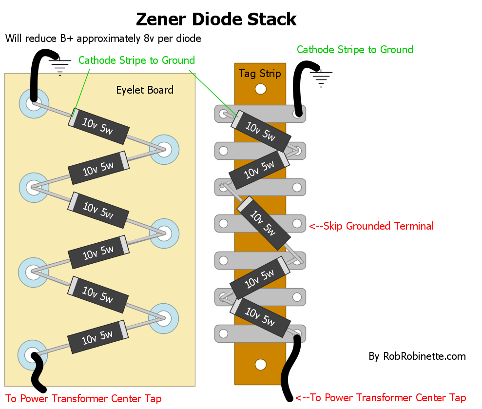
The diode stripe marks the cathode and negative end of the diode. The other end is the + anode. To place a Zener string in the B+ supply wire you would place the cathode stripe toward the rectifier.
One other option to lower B+ voltage is to build an inexpensive 'bucking' transformer to lower your wall AC voltage which will lower all the AC and DC voltages in your amp including the tube heater circuits.
Lower Your 6.3V Heater Current
Most tubes list the required heater voltage as 6.3 volts +/- 10% or 5.7 to 6.9v. Running the heater voltage above 6.3 volts can shorten the life of your preamp and power tubes. Your amp will also run hotter and consume more electricity.
My amp's heater circuit measures 6.8v so it's close to the max allowed. Dropping a half of a volt would be perfect to get the standard 6.3 volts. The 5F6A draws 2.7 amps of 6.3v heater current using 6L6GC and 5881 power tubes (3.9 amps with EL34's) so we can use this equation to calculate what resistors to use to lower our heater voltage. Just place the resistors on the V5 power tube's pins 2 & 7 and attach the inbound heater wires (from transformer or pilot light) to the resistors. I used a small 2 inch x 1.5 inch perf board to mount the resistors.
Desired voltage drop / amps = resistor ohms
.5 volt drop / 2.7 amps = 0.19 ohm dropping resistor
We want to keep the voltage balanced on each heater pin to reduce 60Hz hum so we need to use two resistors, one on each pin
We divide the 0.19 ohm by 2 to get 0.095 ohm (I rounded up to 0.1 ohm)
Note: These same resistors would drop .78v when using EL34 power tubes (3.9 amps * .2 ohms = .78v)
amps * voltage = watts of dissipation
2.7 amps * .5 volts = 1.35 watts so to be safe the two resistors should be rated at 2 watts each.
So we would install two 0.1 ohm 2 watt metal film or wire wound resistors on V5's heater pins (2 & 7) and connect the inbound wire (from the power transformer or pilot light) to the resistors. These two resistors will drop the heater voltage by 0.5 volt. These types of resistors are available at http://www.mouser.com/ for about 50 cents a piece.
Standby Switch 'Pop Reduction' and Current Surge Protection
One modification I highly recommend is replacing the Standby Switch Anti-Pop Capacitor with a resistor across the Standby Switch terminals. It will quiet or eliminate the Standby Switch 'pop' by allowing a small current to flow around the Standby Switch to charge the Filter Capacitors. This prevents a current surge when you close the Standby Switch. It also helps control the fly-back voltage spike from the choke when the Standby Switch opens.
You should always ensure the Standby Switch is in the standby position before powering up the amp. Turn on the Power Switch then wait around 15 seconds for the tube heaters to come up to temp and for the pop resistor to charge the filter caps enough to prevent a current inrush which is what causes the pop. Preventing current inrush should also make your filter caps last longer.
Merlin, The ValveWizard recommends a resistor between 47k (2 watt) or 150k (1watt). I had a 100k 2 watt on hand so I used that. Adding the resistor eliminated all pop for my amp.
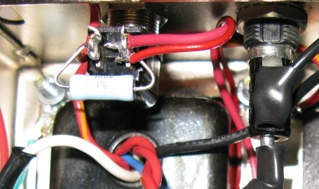
Pop Resistor (grey 100k 2 watt) across the Standby Switch
LED Pilot Light
This simple circuit powers an LED from the 6.3v heater wires.
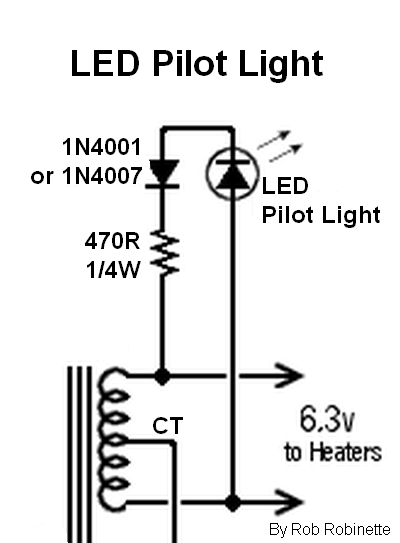
Just use any 1N4001 to 1N4007 diode, an LED and a 470 ohm 1/4 watt (or higher watt rating) resistor connected across the 6.3v heater wires. Note the LED and diode are lined up with their cathodes facing the same direction. The diode has a stripe on its cathode end, the LED's shorter wire lead is the cathode so wire the LED's short cathode wire to the diode's non-striped anode end. Connect the diode's striped end to the 470 ohm resistor. The resistor can actually be connected to either the diode or LED.
The diode rectifies the 6.3v heater AC into DC. The resistor acts as a current limiter. The diode also drops 1.7v of the 6.3v supply leaving 4.6v applied to the resistor and LED. The voltage drop of an LED is about 1.8v to 3.3v and varies by the color of the LED. A red LED drops about 1.8 volts and rises as the light frequency increases. Blue LEDs drop around 3.3 volts. You can reduce the value of the 470 ohm resistor to brighten the LED if it appears dim. A higher resistor value will dim the LED.
Using the Ground Switch Hole for Mods
It's common practice to use the empty chassis hole for the unused and dangerous 'Ground Switch' for modification pots and switches. Be aware that with all the 120v AC stuff nearby (fuse, pilot light, ON/OFF switch) that it's very easy to pick up AC line noise and 60Hz hum there. I recommend you use shielded cable for any signal wire that runs to and from that location. The cable shield should only be grounded at one end to prevent forming a ground loop (ground either end). I like RG174 coax for single signal wire and Canare L-4E5C Mini-Star-Quad Microphone Cable for multiconductor runs like like this to a master volume pot. This Mini-Star-Quad cable has four conductors and a shield.
Pre Phase Inverter Master Volume in the standby switch hole. Notice how multiconductor Mini-Star-Quad shielded cable is used to keep AC noise out from the power transformer and power lines. The cable shield is grounded only at the preamp end to prevent a ground loop. Photo by Mark Herrick.
Protection Mods
These amp protection mods were detailed in a series of articles in Premier Guitar by R.G. Keen.
Power transformer inline pigtail fuses, soft fail rectifier backup diodes on the rectifier tube socket, and spike eating MOV's added between the power tube plates (pin 3) and output transformer center tap.
Fender guitar amp fuses are normally MDL type "slow blow" or "time delay" 1/4 inch (6mm) wide by 1 1/4 inch (30mm) long.
Amp fuses suggested by R.G. Keen: 300 to 500 milliamp slow blow fuse for the 5F6A to the power transformer high voltage center tap (B+ Fuse). 200 to 300 milliamp for a 5E3. 4 amp slow blow fuses added to each 6.3v heater line (2 parallel fuses = 8 amp limit). 4 amp slow blow fuses added to the rectifier's 5v heater lines. I don't recommend a fuse on the power transformer's bias tap because if it blows the power tubes will run away with max current and burn up. I highly recommend you at least install the B+ fuse to protect the power transformer.
If you are concerned about cathode follower grid-to-cathode arcing at startup you can connect this 120v neon bulb between V2B (cathode follower) pins 7 & 8 (grid and cathode). You can also use a 10k 1/2 watt resistor in series with a 1N4007 diode instead of the bulb. Connect the diode stripe (cathode) to pin 8 (cathode). If you start blowing V2 tubes then this is the fix you need.
A cathode follower also puts a strain on the cathode-to-heater voltage limit. It's usually around 100v and a typical cathode follower has around 180v on the cathode and the heater filaments are referenced to chassis ground for a 180v difference. Elevating the heater voltage to around 70v will greatly reduce the strain on the cathode follower heater insulation and also reduce 60Hz heater hum. Creating a voltage divider of the B+2 power node can be done with two resistors and a cap. See the JCM800 6V6 layout for an example.
Voltage spike suppressing 20mm MOV's (metal oxide varistor) installed between the power tube sockets plate pins (pin3) and the output transformer center tap. I used 625v 1.65kv clamping TDK MOV's from Mouser.com. All of these mods help protect your expensive power and output transformers.
Rectifier 'Backup' Diodes
Installing two 'backup' diodes can prevent a dying rectifier tube from frying your power transformer or amplifier circuit with high voltage AC. The diodes pre-rectify the high voltage AC from the power transformer into pulsing DC and feed it to the tube rectifier which will power the amp and give you that loved tube rectifier voltage sag. Having two diodes in series (one solid state and one tube) will also greatly increase the rectifier circuit's peak inverse voltage (PIV) handling capability and should increase the rectifier tube's lifespan. You're rectifier tube should outlive your amp with these backup diodes sharing the load. Here's a quote from the ValveWizard's web page:
If we were worried about running a valve rectifier too close to its maximum Va(rms) [AC voltage rating], we could place one or more silicon diodes having a much higher peak inverse voltage in series with each anode, as protection elements. In theory, the valve rectifier can then be used with supply voltages up to twice the rated Va(rms). The silicon diodes will have no adverse effects on the normal operation of the valve rectifier.
I installed two 1N4007 diodes on the rectifier's pins 3 to 4 and pins 5 to 6. These little 25 cent diodes are rated for 1000 freakin' volts of peak AC (707V AC RMS). Place the diode's stripe (cathode end) on the power outflow side (pins 4 and 6). I attached the power transformer's main output wires to the unused pins 3 and 5 (instead of the normal 4 and 6). The AC power then flows through the diodes to the plate pins 4 and 6. The diodes are cheap insurance and I install them in all my amps.
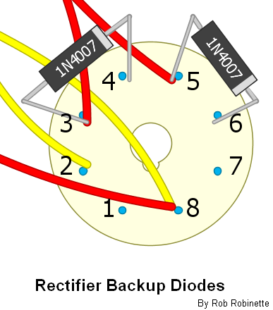
The stripe on the diode indicates polarity.
Installing backup diodes greatly increases the peak inverse voltage (PIV or reverse repetitive maximum voltage Vrrm) handling of the tube rectifier and makes life much easier for the tube rectifier. Should the rectifier tube fail and short out damaging AC will not enter the amplifier circuitry.
No Transformer Center Tap Hybrid Tube Rectifier
This allows you to use a transformer with no center tap with a tube rectifier by installing the 'bridge half' of a bridge rectifier to provide a current return path. Two 1N4007 diodes running from the tube plate pins to ground will do the trick. Diode polarity is important, install the diodes with their stripes to the tube plates.
Hybrid Tube Rectifier With No Center Tap + Backup Diodes
Why would anyone do this--bolt a full bridge rectifier to a tube rectifier? So you can use a transformer without a center tap, extend the life of your rectifier tube, protect the amp from hard rectifier tube failure and get a tube rectifier's vintage voltage drop and sag.
6.3v Heater Artificial Center Tap
Install a 6.3v filament heater artificial center tap (sometimes called "artificial ground"). If your power transformer did not come with a 6.3v heater center tap then you should add an 'artificial center tap' to eliminate 60Hz heater hum. It does this by balancing the voltage between the two heater wires. When each wire carries an equal AC voltage 60Hz hum will be cancelled out by twisting the heater wires together. Unbalanced voltage will allow some hum to leak out. If your power transformer does have a 6.3v center tap (usually a green & yellow wire) then I recommend you use that instead of this 'artificial center tap,' but do not use both real and artificial center taps together. Using both can cause a very noisy ground loop.
You simply connect both 6.3v green heater wires to ground through two 100ohm 1/2 watt resistors. I like to place the resistors on one of the power tube's socket as shown below.
6.3v Filament Heater Artificial Center Tap
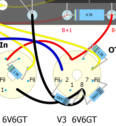
Filament heater artificial center tap consists of two 100 ohm 1/2 watt resistors connected between either one of the power tube socket's pins 2 and 7 (heater wires) and pin 8 (cathode). This works in both cathode bias amps (elevates the heater ground) or fixed bias amps (grounded cathode). Do this only on one power tube. These resistors are not required if your power transformer has a 6.3v center tap.
Humdinger Heater Hum Pot
The Humdinger is an adjustable heater artificial ground. A 100 or 250 ohm linear pot is used to adjust the resistance value between ground reference and the two heater wires to even out their voltage and minimize 60Hz heater hum. You simply adjust the pot by ear for least hum. If you don't notice a change in hum when adjusting the Humdinger then just set it in the middle of the pot travel to equalize the resistance for each heater wire. Remove your current 6.3v center tap before installing a Humdinger.
You can connect the Humdinger to the heater wires anywhere along the heater wire chain. You can use the pilot light or tie it into any one of the tube's heater terminals.
For cathode biased amps you can connect the Humdinger's ground wire to a power tube socket cathode pin (pin 8) or to the hot side of the cathode resistor (as shown in the next section) to elevate the heater reference voltage. A voltage elevated Humdinger can eliminate more heater hum than any other type of heater real or artificial center tap.
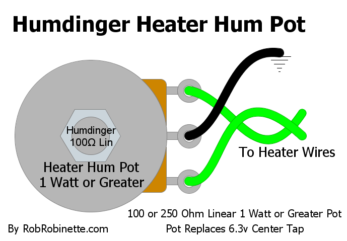
250 ohm linear pot is used to balance the voltage on the two heater wires for minimum hum. A 100 ohm linear pot will work fine too. Instead of connecting the center terminal to ground as shown, connecting it to a cathode biased amp's cathode resistor will elevate the center tap and reduce hum.
Add a 6" Practice Speaker to Your Amp Head
I installed an Eminence 620H 6" hemp coned speaker in my 5F6A amp head. It makes low volume practice easier and adds very little weight. Since it must be offset to the preamp side of the amp it will actually help balance the weight of the amp. Also consider offsetting the amp's carry handle one or two inches toward the heavy end (transformer end) of the chassis (would be left in picture below) to balance the amp during hand carry.
Stealth Eminence 6" 620H 20 watt Hemp Coned Practice Speaker
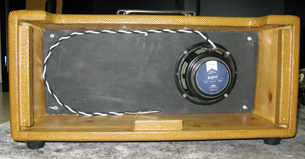
This is a very cool little $55 speaker. It adds very little weight to the head cab. It's mounted on the preamp side to clear the transformers. The custom lacquered tweed cab with baffle was made by John Mergili of www.mergili.com and cost only $259 delivered.
TMB Tone Stack On Pots
This is a point-to-point layout for mounting the 5F6A tone stack components directly to the Treble Middle and Bass (TMB) pots.
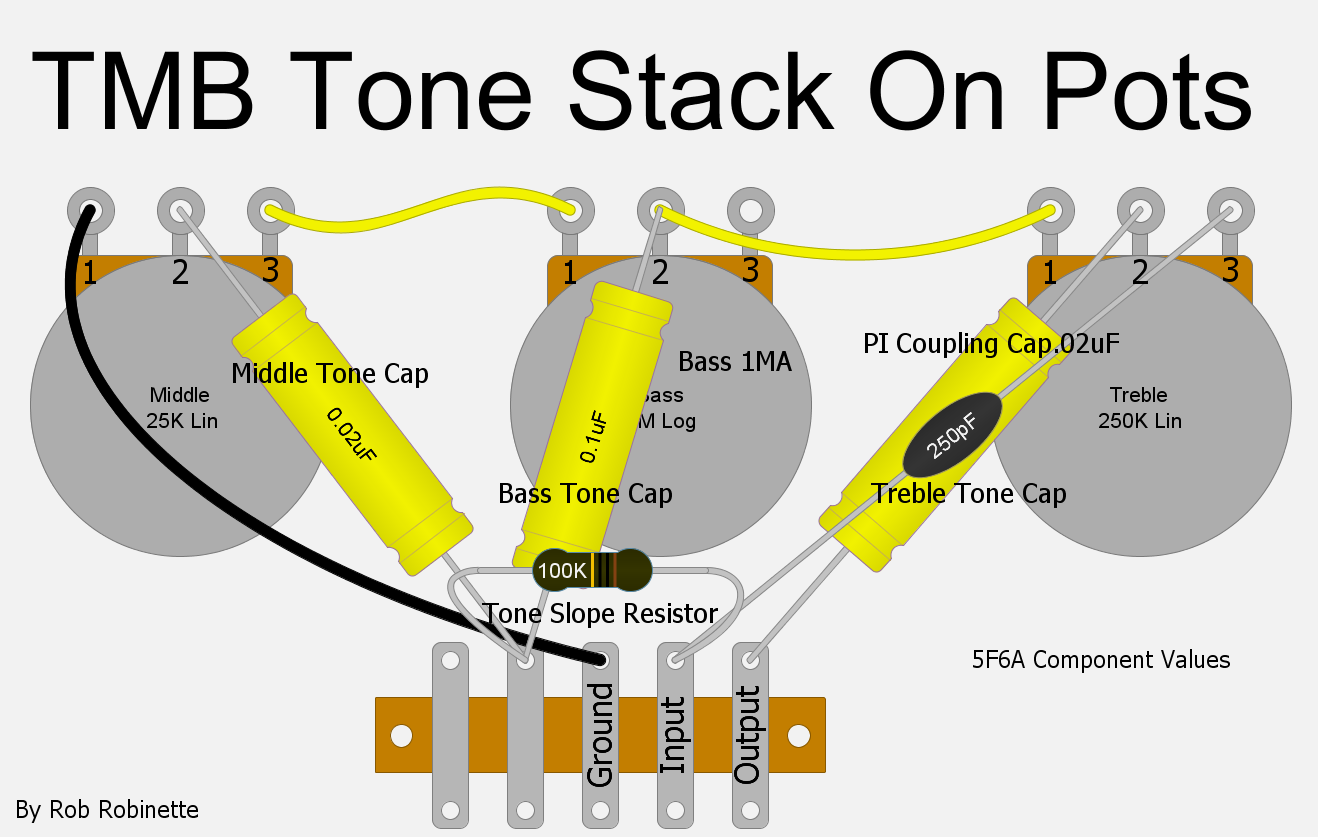
The 5F6A Bassman's TMB tone stack mounted on the pots. A two or three terminal Terminal Strip can be used to secure the 56k Slope resistor. Click the image to see the PDF.
Fixed Mid TB Version
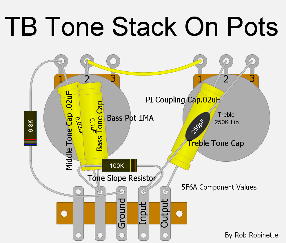
The Middle pot has been replaced with a 6.8K resistor.
Capacitor Outer Foil Markings
If your non-polarized electrolytic capacitors have markings for the outer foil it is best to put the mark on the signal input side for best noise suppression. The 5F6A phase inverter's AC signal shunt cap on V3B's grid should have the marking on the Presence Control end. The Presence Control cap should have the marking on the ground side. My Modern 5F6A Layout diagram at the top of this page shows an 'O' on the outer foil end on all the non-polarized capacitors.
Considerations Before Building a 5F6A
These are some minor upgrade's or tweaks I suggest for a 5F6A build. Some of them are much easier to install during the build.
Consider using 1 watt resistors instead of the standard 1/2 watt. The larger resistors will run cooler which will make them generate less hiss. The amp will also be more reliable in the long, long run. Bump all the plate load resistors up to 2 watts for the same reason except as noted in the next paragraph.
Consider using metal film resistors if you don't care if the circuit board does not look period correct. Metal film resistors generate 1/10th the noise of carbon comp. R.G. Keen recommends metal film for all signal resistors except for the plate load resistor of the stage just before the phase inverter (it's inside the feedback loop) so the V2A 100k plate load resistor and V2B 100k cathode resistors would be a good place to use 1/2 watt carbon composition resistors to ensure "vintage" tone without generating excess noise.
Definitely install an adjustable bias control so you can bias the amp to your personal 'sweet spot.' This will also make it possible to bias 6V6, EL34 and KT66 & 88 power tubes. Consider a balanced bias control so you can separately bias each power tube.
Using a multi-tap output transformer with 2, 4 and 8 ohm speaker taps will make it easier to use extension cabs with your Bassman.
Use a power transformer with 4 or more amps of 6.3 volt heater current so you can run EL34, KT66 and KT88 power tubes.
Us a power transformer with a 6.3 volt center tap so you won't have to install an artificial center tap.
Bump the watt rating of the 470 ohm 1 watt power tube screen resistors (mounted on the power tube sockets) to 5 watts. These resistors are common failure points and a beefier resistor will work better with EL34 power tubes if you choose to run them.
Upgrade the two tiny 8uF bias circuit filter caps to 50uF to reduce 60Hz hum. Modern tube amps use these large filter caps and they will not affect the amp's tone in any way.
Install an extra eyelet or turret near the V1 cathode resistor so you can use separate cathode resistors for V1A and V1B. This allows you to voice the two channels differently by using two different value bypass capacitors.
Install an extra eyelet or turret next to the positive end of the feedback resistor for a future 3-way Negative Feedback Switch.
Install jumpers from pins 1 to 8 on your power tube sockets. This will make the sockets compatible with EL34 power tubes. You can even do this before installing the sockets in the chassis.
Install 'Backup Diodes' on the rectifier tube socket to extend the life of the rectifier tube and protect the amp from a rectifier short failure. Install a power transformer high voltage center tap in-line fuse to protect your expensive power transformer.
Run the wire from the bias output to the power tube 220k grid resistors over the top of the board instead of under it. This will make several modifications much easier since you won't have to pull the board to access the wire.
Install an extra eyelet or turret to separate the two 220k power tube grid resistors. This will allow you to install a balanced adjustable bias circuit or add a dual pot post phase inverter master volume (PPIMV).
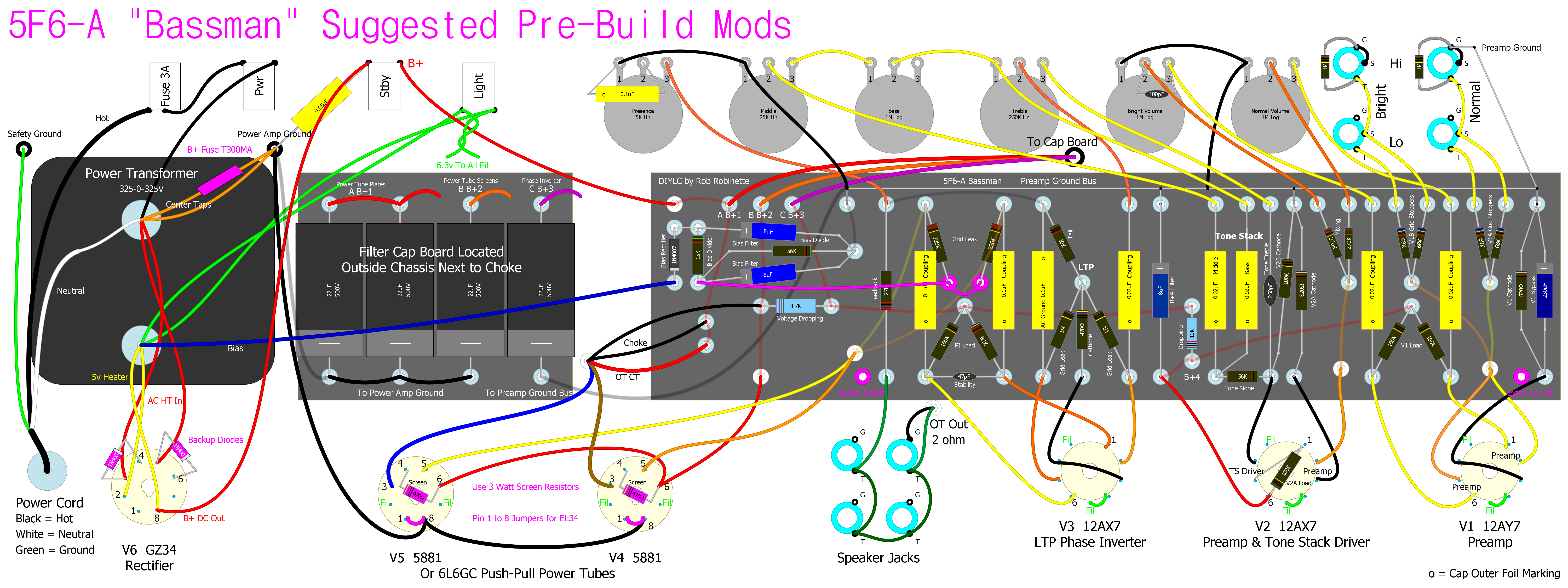
Click on graphic to see the full size and readable image. PDF is available here. Download the Hoffman Circuit Board DIYLC file with Filter Cap Board. You can upload these files to Doug Hoffman's (HoffmanAmps.com) DIYLC file analyzer and he can make a turret or eyelet board for you.
Speaker Suggestions
With between 30 to 45 watts of output (depending on the B+ voltage and the type of power tube) the 5F6A will need speaker(s) rated for 50 to 75 watts to safely run the amp wide open. You can run a single 75 watt, two 30 watt or four 15 watt speakers safely.
My favorite tweed speaker is the Weber 12A125A which is a Fender tweed vintage style 12" AlNiCo (Aluminum, Nickel and Cobalt magnet) speaker but it's underpowered at 30 watts as a single Bassman speaker but would work with the 5F6A in a 2x12 or 4x12 cab. The 12A150 has a larger 1.5 inch voice coil and higher 50 watt rating so it can easily handle a Bassman's output in a 2x12. The 10 inch, 30 watt Weber 10A125 AlNiCo is my favorite for a 4x10 or 2x10 Bassman cab. It gets great reviews and gives probably the most authentic tweed Bassman tone.
The Weber 10A150 (50 watt, larger 1.5 inch voice coil) and 10A125S (30 watt, 1.25 inch voice coil but with smooth cone and slightly different voicing) are also popular. If you're on a budget check out the Weber Ceramic Signature 25 watt speakers at $44. If you do go with Weber I recommend you have Weber break their speakers in for you so they will sound great right out of the box.
Other popular 10 inch Bassman speakers are the Eminence 10516 16 ohm and 1028K 8 ohm speakers. The WGS Veteran 10 at $41 each and rated at 95dB are also popular.
Many people mix and match their 4 speakers. Going with two Weber 10A125's and two WGS Veteran 10's could add some sonic complexity.
If you are building a head cab consider installing an Eminence 6 inch 20 watt hemp coned 620H speaker. It won't add much weight but it sounds great and you'll always be ready for low volume practice.
Stealth Eminence 6" 620H 20 watt Hemp Coned Practice Speaker
This is a very cool little $55 speaker. It adds very little weight to the head cab. It's mounted on the preamp side to clear the transformers and actually helps balance the amp's weight. The custom lacquered tweed cab with baffle was made by John Mergili of www.mergili.com and cost only $259 delivered.
For my 5E3 Deluxe clone I installed a 15" JBL E130 reconed with hemp by A. Brown Speaker Repair. It's a very accurate, efficient and loud speaker which makes it ideal for gigging. The hemp cone tames the brittleness of the standard E130 and it just sounds freakin' great. The downsides are I get no speaker breakup and the amp is crazy heavy but the 5F6A sounds fantastic through the hemp coned E130.
15 Inch Hemp Reconed JBL E130
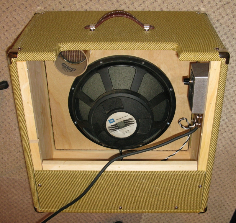
Note the cool green tint of the big 15 inch hemp cone. The speaker is very efficient (and loud) at 105dB SPL and is rated at 300 watts. This amp can keep up with any drummer. Carl's Custom Guitar's Speaker Soak attenuator installed at upper right to allow for less-than-ear-splitting practice. The cab is a 5E3 combo but it's vented and sized so it can also be used as a sealed back extension cab (you can't seal the back and run the 5E3 due to heat buildup).
British Voiced Marshall JTM45 Speakers
If you prefer a more Marshall JTM45ish tone here's my suggestions:
The Marshall Bluesbreaker amp was a JTM45 in a 2x12 cab with 15 watt AlNiCo speakers so the suggested 60 watt minimum rating is not a hard and fast rule. For a Bluesbreaker tone I'd go with the Celestion Golds but the Bluesbreaker Reissue comes with Celestion G12M's.
The standard JTM45 speaker pairing is a quad or pair of "Green Back" speakers like the Celestion G12M or G1275H, Scumback H75 or H55 12" or WGS Veteran 30. Some people rave about 2x12 15 watt Celestion Blues.
5F6A Thermal Image
I have a Seek Thermal Imaging camera so I thought I'd take a pic of the 5F6A '59 Bassman chassis at idle temperature so we can see what's hot and what's not. I was surprised to see the power tubes are hotter than the rectifier tube.
5F6A Chassis Thermal Image
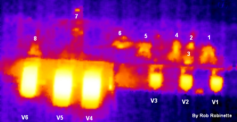
1. V1 Load Resistors 2. V2B Cathode Resistor. 3. Socket mounted V2A Load Resistor. 4. B+4 Voltage Dropping Resistor. 5. Phase Inverter Load Resistors. 6. B+3 Voltage Dropping Resistor. 7. Pilot Light. 8. Rectifier Socket mounted Backup Diodes and 0.01uF 3KV (3000V) disk capacitor. All the load resistors and V2B cathode resistor run hot and would benefit from an upgrade to 1 watt resistors. Cooler running resistors generate less hiss.
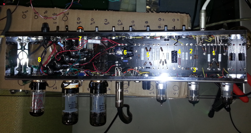
I was surprised to see the power tubes V4 and V5 are actually hotter than the rectifier tube V6.
How the Bassman Works
Annotated Schematic With Signal Flow and Component Function
What do all those parts do? Click on the graphic to see the full size and readable schematic. Most original 5F6A Bassman's actually use a 100k Tone Slope resistor, .1uF Bass Tone cap and different presence circuit than shown in this Fender schematic.
The Bassman's job is to take the tiny electrical signal from a guitar and build it up until it's strong enough to move a speaker cone. The guitar's alternating current (AC) signal voltage enters the amp at the upper left Bright Hi jack, flows through both 68k grid stopper resistors (34k parallel resistance) on its way to the V1B (valve 1 second half). The input resistor on the Hi input jack sets the amp's input impedance and acts as the V1B grid leak resistor. The grid stopper resistors remove high frequencies beyond human hearing which helps stabilize the amp. The grid stopper resistors also function as mixing resistors to prevent two instruments from interacting with one another. Dropping the value of the grid stoppers to 16k or even lower can add some top end sparkle.
Preamp tube V1B gives the Bright channel guitar signal its first gain boost. Its cathode resistor is shared with V1A (Normal channel preamp) and has 820 ohms of resistance which is equivalent to 1640 ohms for a non-shared cathode resistor. The lead channel voice mod gives V1A and B their own cathode resistor so the lead channel can be biased cooler with a 2.7k resistor. This cooler bias gives earlier breakup and smoother sounding asymmetric distortion. Some Marshall amps have one channel biased hot with an 820 ohm cathode resistor and the other biased cool with a 2.7k resistor.
V1B's cathode resistor is bypassed with a huge 250uF bypass cap which increases gain for all frequencies including low bass guitar freqs. Many Fender tweed amps use a 25uF bypass cap which will still boost all guitar freqs. Many modern amps use a tiny .68uF bypass cap which boosts only mid and upper freqs. My 5F6A lead channel voice mod uses a .68uF bypass cap for one channel.
The guitar signal flows out the first stage preamp tube's plate (anode) through the first coupling cap which blocks the plate's high voltage DC but lets the AC guitar signal pass. The uF (micro Farad) value of the coupling cap controls the preamp's low end frequency cutoff. The 5F6A's .02uF caps are relatively large to support the amp's original purpose--bass guitar. Reducing their value will "raise the floor" and tighten up the clean and especially the overdrive tone. Many modern amps use .0047uF (1/5th the size of a .02uF) coupling caps. Amplifying low frequencies requires more energy than mid and highs so removing some bass from the guitar signal keeps the amp from wasting its power to amplify those unneeded low freqs giving you more headroom with louder, cleaner mids and highs.
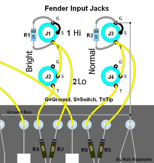
R1 and R2 are the 1 mega ohm input resistors. R3, R4, R5 and R6 are grid stopper resistors. See this link for everything you ever wanted to know about how Fender input jacks and jumpering works.
The volume pot control is a variable voltage divider that controls volume by bleeding some signal to ground and the bright cap bypasses high frequencies around the volume control to keep the tone bright at low volume settings. The lower the volume the more prominent the bright cap's effect becomes. The 5F6A's bright cap is very small at 100pF (pico Farad). Most amps use a 250 or 500pF bright cap to lower the cutoff frequency and allow more mids to bypass the volume control. A common 5F6A mod is to use a 500pF bright cap to brighten the overdrive tone. The bright cap is the only difference between the bright and normal channels and at maximum volume there is no difference between the channels. This is why you may want to voice one of the channels differently. My voice mod reduces the value of the coupling cap, bypass cap and adds a 500pF bright cap to tighten and modernize the tone of one channel.
After the volume pot the guitar signal flows through a 270k mixing resistor. The two mixing resistors reduce the normal and bright channels' interaction. Some amps place a "bright cap" around the mixing resistors to keep the tone from being dulled by the high value mixing resistors. The mixing resistor also functions as the V2A grid stopper.
Next the signal moves into the V2A preamp for another gain boost. It leaves through the plate and goes directly onto V2B's grid (DC coupled with no coupling cap). The primary purpose of the V2B Cathode Follower is to prevent the tone stack from loading down the high impedance guitar signal coming off V2A's plate. The Cathode Follower supplies a low impedance signal to the tone stack to keep the tone controls from affecting the amp's output volume too much. Amp users do not want the volume to drop when they roll off some bass.
But the Cathode Follower does much more than feed the tone stack. It is the first triode to go into overdrive and its interaction with the upstream gain stage adds a unique overdrive effect that limits clipping of both the positive and negative signal lobes. This is one of the "secret" reasons the Fender 5F6-A Bassman, Marshall JTM45, Plexi and Master Volume amps sound so good when pushed hard.
Notice the signal leaves V2B through it's cathode, not plate. The signal then flows through the tone stack. All three tone stack capacitors act as coupling caps to keep V2B's high cathode voltage from flowing downstream. See How the TMB Tone Stack Works for more info.
After the tone stack another coupling cap does the opposite of a normal cap--it keeps the voltage on the long tail pair phase inverter grid (around 30 volts) from flowing upstream to the tone stack pots. The phase inverter splits and amplifies the guitar signal to drive the two power tubes. The signal enters at V3A's grid and flows out its plate through a coupling cap and onto power tube V4's grid. This signal has been inverted during amplification. V3A's signal also flows through its cathode to V3B's cathode and is amplified and passed out the plate to a coupling cap and power tube V5's grid. This signal is not inverted so the signals flowing to the two power tubes are 180 degrees out of phase--one is inverted and one isn't. See How the Long Tail Pair Works for more info.
The power tubes amplify the mirror image signals and while one tube plate is "pushing" the signal through the output transformer primary winding (coil), the other power tube is "pulling" it. The signal is pushed and pulled through the output transformer's primary winding where it generates magnetic flux that flows around the transformer's iron core and creates a voltage in the secondary winding. The transformer's main job is to transform the very high voltage but very low current guitar signal (high impedance) from the power tubes into a low voltage but high current signal (low impedance) the speaker's voice coil needs.
The low voltage, high current AC guitar signal flows through the speaker's voice coil and creates a magnetic field that interacts with the speaker's magnet to push and pull the speaker cone which creates the air pressure waves our ears perceive as the sweet sound of electric guitar. For every guitar string movement there is a corresponding speaker cone movement.
For more detail on how amps and tubes work see the How Tube Amps Work page. See Tube Guitar Amplifier Overdrive for specific information on how overdrive distortion is created.
The 5F6A's output signal stays clean to around 1/4 turn of a volume knob with an average guitar input signal. Hot pickups will bring on distortion earlier and of course low output vintage style pickups will stay cleaner at a higher volume knob setting. The power tubes are the first part of the circuit to distort followed by the phase inverter and then second preamp stage (Neumann and Irving 2015). Even at maximum volume the overdrive behavior of the 5F6A stays controlled with no blocking distortion evident. Early power tube distortion and max volume circuit composure are hallmarks of the famous 5F6A overdrive tone. For more information on overdrive see my Overdrive webpage.
Annotated Layout With Signal Flow
Notice how convoluted the signal flow is compared to the schematic above. Click on the graphic to see the full size layout.
For a more detailed circuit analysis of the 5F6A see this summary by Richard Kuehnel and even more detail in his book, Circuit Analysis of a Legendary Tube Amplifier: The Fender Bassman 5F6-A. I purchased and read the book but some of it is geared toward the electrical engineer but if you're a 5F6A fanatic like me you need a copy.
How the Long Tail Pair Phase Inverter Works
The Long Tail Pair (LTP) Phase Inverter (also called the cathode-coupled phase inverter) is the most popular phase inverter in guitar amplifiers due to its large output voltage swing and sweet overdrive tone. Unlike the cathodyne phase inverter in the 5E3 Deluxe with a gain of less than 2, the LTP phase inverter not only creates a dual mirror image signal stream but it also acts as a gain stage boosting the signal by about 1/2 of a normal triode gain stage (typically a gain of 30). This added gain gives its output more voltage swing to drive big bottle power tubes to a fully distorted state. The LTP is a true differential amplifier that amplifies the difference between its two grids. It uses both halves of a dual triode tube (usually a 12AX7 or 12AT7).
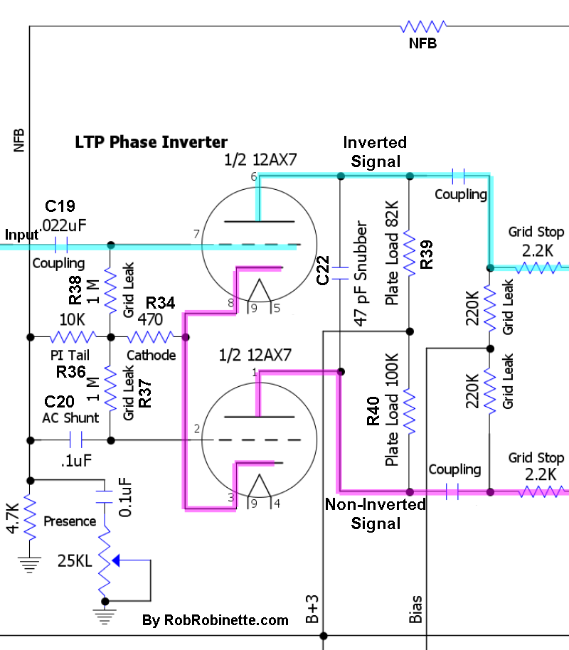
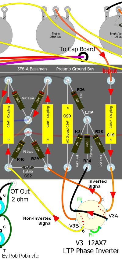
Signal flow shown with red arrows. Component numbers on the schematic and layout match. The signal enters the phase inverter at V3A's grid and flows out both its plate (inverted signal) and cathode (non-inverted signal). The cathode signal flows to V3B's cathode where it is amplified.
For simplicity I will refer to the upper V3A triode as the "upper triode" and V3B as the "lower."
The upper triode in the schematic above has a dual function. It acts as a normal gain stage by outputting an inverted signal at its plate but also acts like a cathode follower by outputting a non-inverted signal at its cathode.
In the schematic above the AC input signal flows through coupling capacitor C19. Cap C19 blocks the upper triode's 32.5v of DC grid voltage out of the tone stack. This grid voltage is generated by the voltage drop across the R36 tail resistor. The signal then flows onto the upper grid while the lower grid is held at a constant DC voltage and all AC signal is sent to ground through shunt capacitor C20. C20 also passes the negative feedback signal to the lower triode's grid. C20's third function is to act as a coupling cap to handle the DC voltage across the R36 tail resistor.
The upper and lower triode cathodes are tied together. All of the lower triode's guitar signal flows from the upper triode's cathode. With the lower grid held constant, signal voltage fluctuations on the lower cathode alter the electron flow from it to the plate which creates an amplified signal on the lower triode plate.
R36 is the tail resistor that creates the relatively high voltage (34v DC in the Bassman) needed for the cathode follower function of the upper cathode. It also supplies a near constant current flow shared between the two cathodes--as current increases through the upper cathode the current decreases through the lower and vice versa.
R34 is a standard bias resistor and creates a 1.5 volt difference between both tubes' grid and cathode. Its 470 ohm value shared between the two cathodes.
R37 and R38 are simply grid leak resistors which leak off DC grid current to maintain a steady DC bias voltage between the grid and cathode.
The plate load resistors R39 and R40 are different values to balance the difference in gain between the upper and lower triodes.
The negative feedback signal from the output transformer's 2 ohm speaker tap is injected into the LTP phase inverter in two places: the lower grid through C20 and at the R36 tail resistor which leads to the cathode. The negative feedback signal on the lower grid is in phase with the primary signal on the upper grid and counteracts the signal resulting in negative feedback attenuation. Injecting the NFB signal at the tail resistor helps balance the feedback effect on the upper and lower plates.
The Presence control (R35 and C21) removes a variable amount of high frequency from the negative feedback signal. Reducing negative feedback has the effect of boosting output so reducing the high frequencies in the negative feedback signal boosts high frequency output. C21 shunts high frequency AC NFB signal voltage to ground. Increasing C21's capacitance value will lower the cutoff frequency and bypass a larger range of frequencies to ground therefore boosting a larger frequency range at the speaker output.
Capacitor C22 suppresses oscillations above audio frequencies between the two triodes' plates to help stabilize the circuit.
LTP and cathodyne phase inverters present a very high impedance to upstream circuits because their grid leak resistors are "bootstrapped" to the phase inverter tail resistor. The input signal on the grid is also present at the top of the tail resistor. This in-phase tail resistor signal reduces signal loss through the grid leak resistor which greatly reduces the load shown to the previous gain stage. Since impedance affects an audio filter's corner frequency we must use a much smaller coupling cap at the phase inverter grid to get the same low frequency roll off. The .022uF phase inverter coupling cap used in the 5F6A could easily be reduced to .002uF with no effect on tone but decrease the likelihood of encountering blocking distortion.
Function Detail: When a positive voltage signal arrives at the upper grid the reduction of blocking negative electrons on the grid allows electrons to flow from its cathode, through the grid, to its plate. The electrons flowing onto the plate lowers the plate voltage--this is the inverted and amplified output signal. As electrons leave the upper cathode a positive voltage is created on the cathode (scarcity of electrons = positive voltage) caused by the voltage drop across the cathode resistor R34. This positive signal voltage is also present in the lower cathode because the two cathodes are directly connected. Since the lower grid is held constant at 0 volts AC, any change in its cathode voltage will create a voltage difference between the grid and cathode. This voltage difference changes the flow of electrons from the cathode, through the grid to the plate. As the lower cathode goes positive (scarcity of electrons) fewer electrons will flow from it through the grid to the plate. The reduction of electrons flowing onto the plate raises the plate voltage--this is the non-inverted and amplified output signal.
Bassman 5F6-A LTP Phase Inverter Idle Voltage
Note the voltage difference between the resistor junction of 32.5v and the cathodes at 34v equaling a normal bias for a 12AX7 of 1.5v. The voltage difference between the grids (22 and 23v) and the resistor intersection (32.5v) is measurement error caused by voltage probe circuit loading (if it were real the triodes would be in cutoff). Both grid voltages are actually the same as the resistor intersection at 32.5v for a bias voltage of 1.5v.
Fender Mid-Production 5F6A Circuit Changes
In April 2017 I received an email from Blake Fowers who was in the process of researching his 5F6A clone build. He found that some 5F6A amps came from the factory with several differences from the Fender schematic and layout. At some point during the 5F6A Bassman's production Fender changed the phase inverter and presence circuits. They changed the phase inverter tail resistor from a 10k 1/2 watt resistor to a 6.8k 2 watt. Increasing the watt rating reduces resistor hiss and the lower tail resistance will boost phase inverter gain. Lowering tail resistance also alters the LTP phase inverter balance. The phase inverter's plate load resistors are 82k and 100k in an attempt to balance the output of the two phase inverter triodes but 87k and 100k are the actual correct values to completely balance the phase inverter output. The lower an LTP phase inverter's tail resistance the more imbalanced its two triodes become so dropping the tail resistance from 10k to 6.8k will add imbalance and make the 82k/100k plate load resistors more appropriate and lead to a more balanced phase inverter. The closer balance will slightly reduce harmonic distortion which can lead to a cleaner, more sterile guitar tone. You can add a 22k resistor in parallel with the 10k LTP tail resistor to equal 6.8k.
Fender also modified the presence circuit to prevent "static" when adjusting the pot and to make it more adjustable. A 4.7k resistor was added across a 25KL presence pot (not a 5KL pot as shown on the schematic). The resistor is physically located on the back of the presence pot and is connected from pot input terminal to ground (back of pot). The presence cap is wired so that it is between the pot and ground so it blocks all DC current through the pot to eliminate "static" when the pot is adjusted.
I have also learned that the actual tone stack values can differ from the schematic. The Tone Slope resistor can be 100k instead of 56k and the Bass Tone cap can be .1uF instead of the schematic's .02uF.
I really shouldn't call this section "mid-production" because these circuit tweaks seem to have been made early in the 5F6A production run because they are seen in almost every original tweed Bassman and Twin chassis photo available. If you have an original 5F6A please let me know if your amp has the extra 4.7k resistor on a 25KL presence pot, a 6.8k phase inverter tail resistor, 100k slope resistor or .1uF Bass Tone cap.
These updates are used in the Fender 59 Bassman Reissue and are shown on my 5F6A Layout at the top of this webpage.
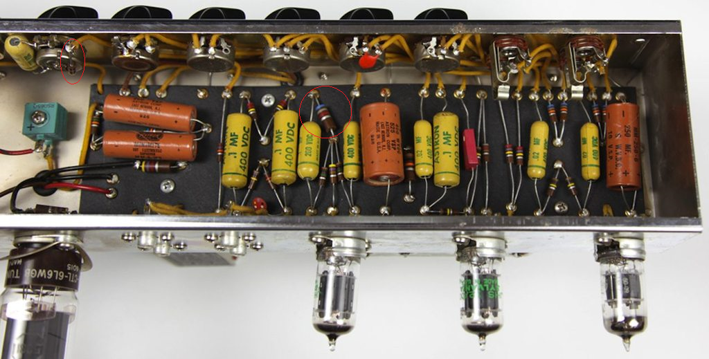
Added 4.7k presence resistor on 25KL Presence pot at far upper left (circled) and 6.8k 2W LTP phase inverter tail resistor at center. You can also see the large .1uF Bass Tone cap and 100k Tone Slope resistor. Photo by Blake Fowers.
5F6A Power Transformer Calculations
The following calculations assume a 325-0-325V power transformer, a GZ34 rectifier tube, two 5881 power tubes and 3 preamp tubes (6 triodes).
5V Rectifier Heater Current
The 5F6A Bassman's GZ34 rectifier uses 1.9 amps of 5V heater current. Other rectifiers: 5Y3 uses 2 amps and the 5U4 uses 3 amps. 5V power usage = 5V * 1.9 amps = 9.5 watts
6.3V Heater Current Calculations
Heater current in amps: Preamp tubes: 0.3, KT88/6550: 1.6, KT66: 1.3, EL34/6CA7: 1.5, 6V6: 0.45, EL84/6BQ5: 0.8, 6L6: 0.9, 5881: 0.9
Calculated 6.3V filament current: (2 * 6L6) + (3 * preamp tubes) = (2 * 0.9) + (3 * 0.3) = 2.7A
6.3V power usage = 6.3V * 2.7 amps = 17 watts
B+ Current Calculations
B+ current is supplied by the power transformer's high voltage secondary. Preamp tube current is so low it isn't necessary to actually calculate the value so we can simply estimate it at 3.6ma per triode (2 triodes per preamp tube).
Power Tube B+ Current Calculations:
Transformer voltage: 325-0-325 volts AC RMS. The 0 means the transformer has a grounded 0 volt center tap and the transformer puts out +325v on one wire while simultaneously putting out -325v on the other for a 650v AC RMS voltage wire-to-wire (650v AC RMS = 1839 volts AC peak-to-peak!)
Max_Plate_Dissipation in watts from tube data sheets: KT88/6550: 42, KT66: 25, EL34/6CA7: 25, 6V6: 12, EL84/6BQ5: 12, 6L6GC: 30, 6L6WGB/5881: 23, 6L6/G/GA/GB/WGA/5932: 19
Rectifier_Efficiency: Solid state full wave diode: 1.37, GZ34: 1.36, EZ81: 1.30, 5U4B: 1.28, 5Y3: 1.25 A solid state diode rectifier only drops 1.4 volts during operation but a 5Y3 will drop around 60 volts.
Unloaded_B+ voltage = Transformer AC * Rectifier_Coefficient = 325V * 1.36 = 442V. This would be the B+ voltage with no preamp or power tubes installed.
B+_Voltage_Drop under load is estimated at 7% = 442 * .07 = 30.9V
How far the B+ drops is dependant upon the output transformer's current rating. A transformer operating near its max current rating can't refill the filter (reservoir) capacitors as quickly as a larger, higher rated transformer so the voltage will drop more.
B+_Voltage = Unloaded_B+_Voltage - Loaded_Voltage_Drop = 442 - 30.9 = 411.1
Calculated_Load = B+^2 / Max_Plate_Dissipation = 411.1V^2 / 23w = 7347 ohms
Notes: Calculated_Load is the ideal plate-to-plate impedance of the output transformer. ^2 means squared.
Power_Tube_Power = (Number_Power_Tubes * (B+ – 30)^2) / Calculated_Load
= (2 * (411.1V – 30V)^2 / 7347 ohms = 39.5 watts
Note: Total amp power output. B+ is the max plate voltage and 30V is the minimum plate voltage for a fixed biased amp, so B+ -30 is the maximum plate voltage swing. For a cathode biased amp we would use 100V for the minimum plate voltage.
Power_Tube_Current = Power_Tube_Power / B+ = 39.5w / 411.1V = 96.2 milliamps
Calculated_B+_Current = Power_Tube_Current + (3.6ma * Number_Preamp_Triodes)
= (96.2ma + (3.6ma * 6) ) = 117.8 milliamps
B+_Power = .1178A * 411.1V = 48.4 watts (this is B+ power used, not output power)
So the power transformer for a 5F6A using 5881 power tubes must supply at least 1.9 amps of 5V rectifier heater current, 2.7 amps of 6.3V current for the tube heaters and 118 milliamps (0.118 amps) of B+ current at idle (with no input signal).
5F6A power transformer power output = 9.5 watts of 5V power, 17 watts of 6.3V power and 48.4 watts of idle B+ power for a total of 69.7 watts, less than a 75 watt light bulb.
The same calculations using 6L6GC power tubes with their 30 watt dissipation rating gives 147ma of B+ current and 60.4 watts of power with a Calculated_Load of 5632 ohms.
See my Amplifier Power Transformer Calculations spreadsheet to automate these calculations.
The Marshall JTM45
The JTM45 was an almost exact copy of the 5F6A.
Differences between the 5F6A and the original JTM45
The JTM45 was a head unit where the 5F6A came only as a 4x10" combo.
The JTM45 uses a higher gain 12AX7 in V1 where the 5F6A uses a 12AY7.
The JTM45 has 2.8 times more negative feedback because the feedback source is from the 16 ohm speaker tap where the 5F6A uses a 2 ohm tap. The extra feedback changes the amp's playing dynamics by tightening the line between clean and overdrive. The extra feedback also changes the overdrive tone and is the main reason many rockers prefer the JTM45 over the 5F6A. This is why I installed the 3-way 5F6A/5E3/JTM45 Negative Feedback Switch on my 5F6A. The feedback level, a 12AX7 in V1 and speakers cause most of the tonal differences between the 5F6A and JTM45.
The JTM45 used a 6.6k output transformer with 8 and 16 ohm taps (and a 100v tap) where the 5F6A used a 4k with just a 2 ohm speaker tap.
The JTM45 used a beefier power transformer so there's a little less voltage sag.
The JTM45's voltage dropping resistor after the choke is 8.2k where the 5F6A used a 4.7k. This lowers the JTM45's voltages to the phase inverter and preamp slightly which would slightly reduce headroom and make life a little easier on the tubes.
The JTM45 head was usually paired with Marshall closed back speaker cabs with "Green Back" speakers which define the "British" tone.
Installing a 12AX7 in V1, adding a feedback switch for the JTM45 negative feedback level and using a Marshall style closed back cab will get you a very JTM45 tone out of a 5F6A Bassman. If your Bassman has adjustable bias you can even install a pair of KT66's or EL34's.
Conversely, if you have a JTM45 you can put a 12AY7 in V1, add a negative feedback switch for 5F6A feedback level (75K feedback resistor = 5F6A feedback), play through a Fender style open back cab and speaker (USA voiced Alnico) you will get a very 5F6A tone. You can even pop in a set of 5881 or 6L6 tubes for the final touch.
Later versions of the JTM45 had these additional differences:
The JTM45's bright cap was increased from 100pF to 500pF to increase the bright boost.
The JTM45 has a 500pF bright cap across the bright channel's 270k mixing resistor to reduce the amount of high frequencies dulled by the mixing resistor.
Almost Identical Marshall JTM45
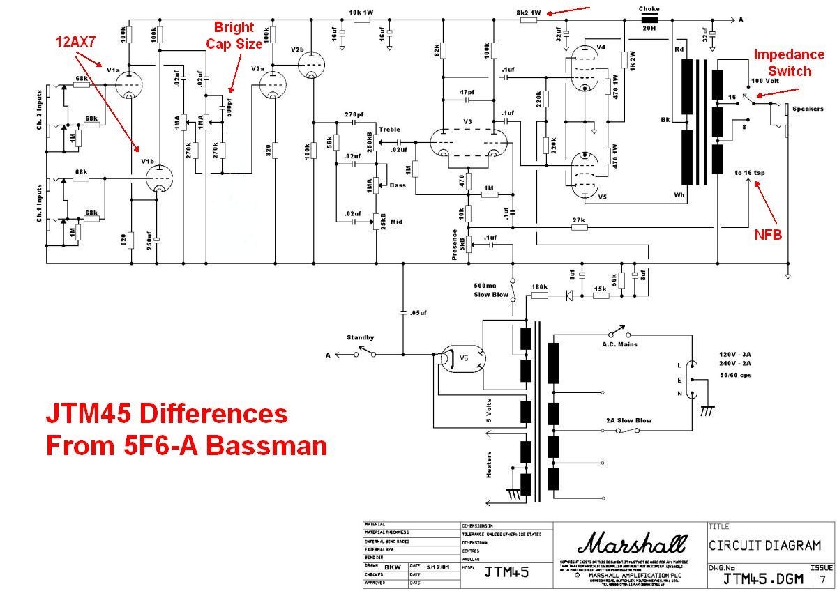
Click on the graphic to see the full size and readable schematic.
59 Bassman Reissue
Many of the mods on this page apply to the Bassman Reissue. Here's the schematic and layout to locate the components:
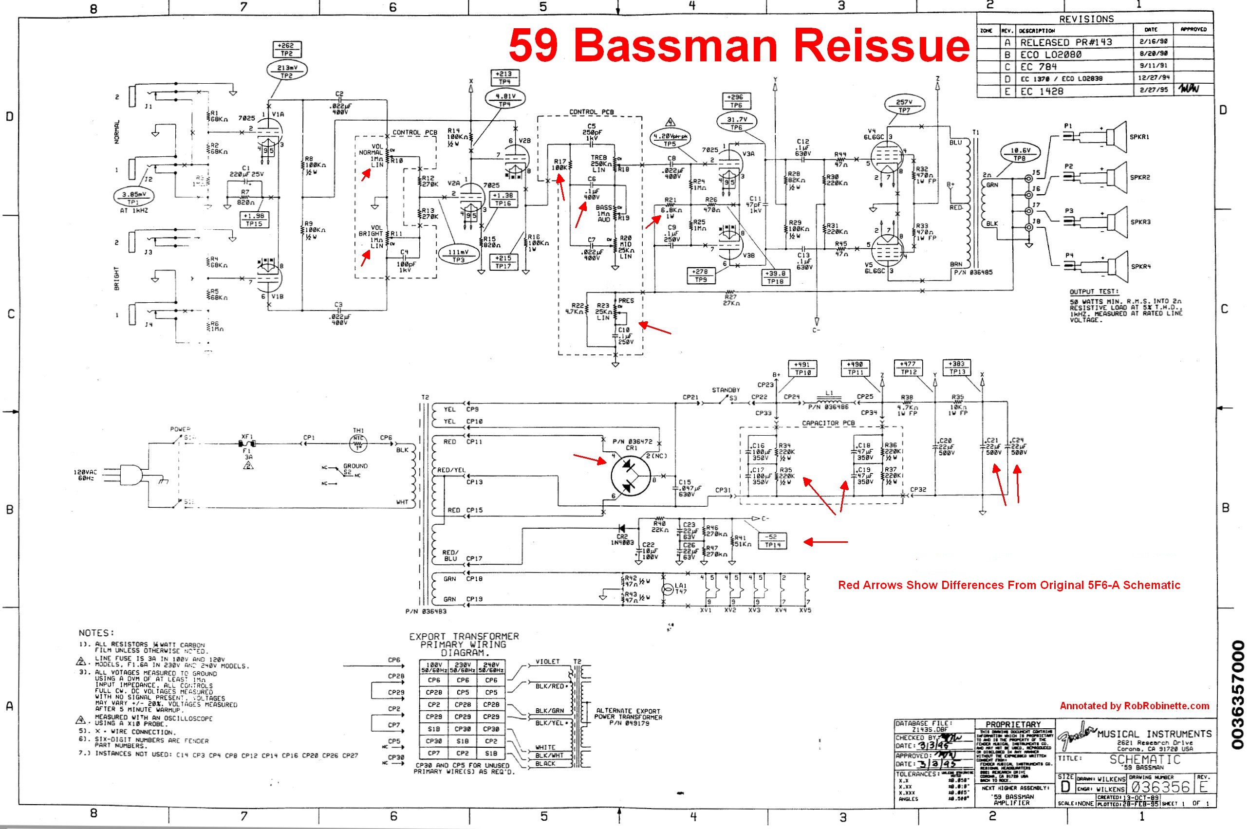
Red arrows show changes from the original 5F6-A Bassman schematic. The 100k Tone Slope resistor, .1uF Bass Tone cap, 6.8k 2 watt Phase Inverter Tail resistor and presence circuit match how most original 5F6-A Bassmans left the factory. True differences from the original 5F6-A are: Volume pots are linear instead of audio, solid state rectifier is used instead of a tube, series first node filter caps are used for an equivalent of 50uF 700v instead of 40uF 600v, preamp filter caps of 44uF instead of 8uF and a completely different bias circuit.
59 Bassman Layout
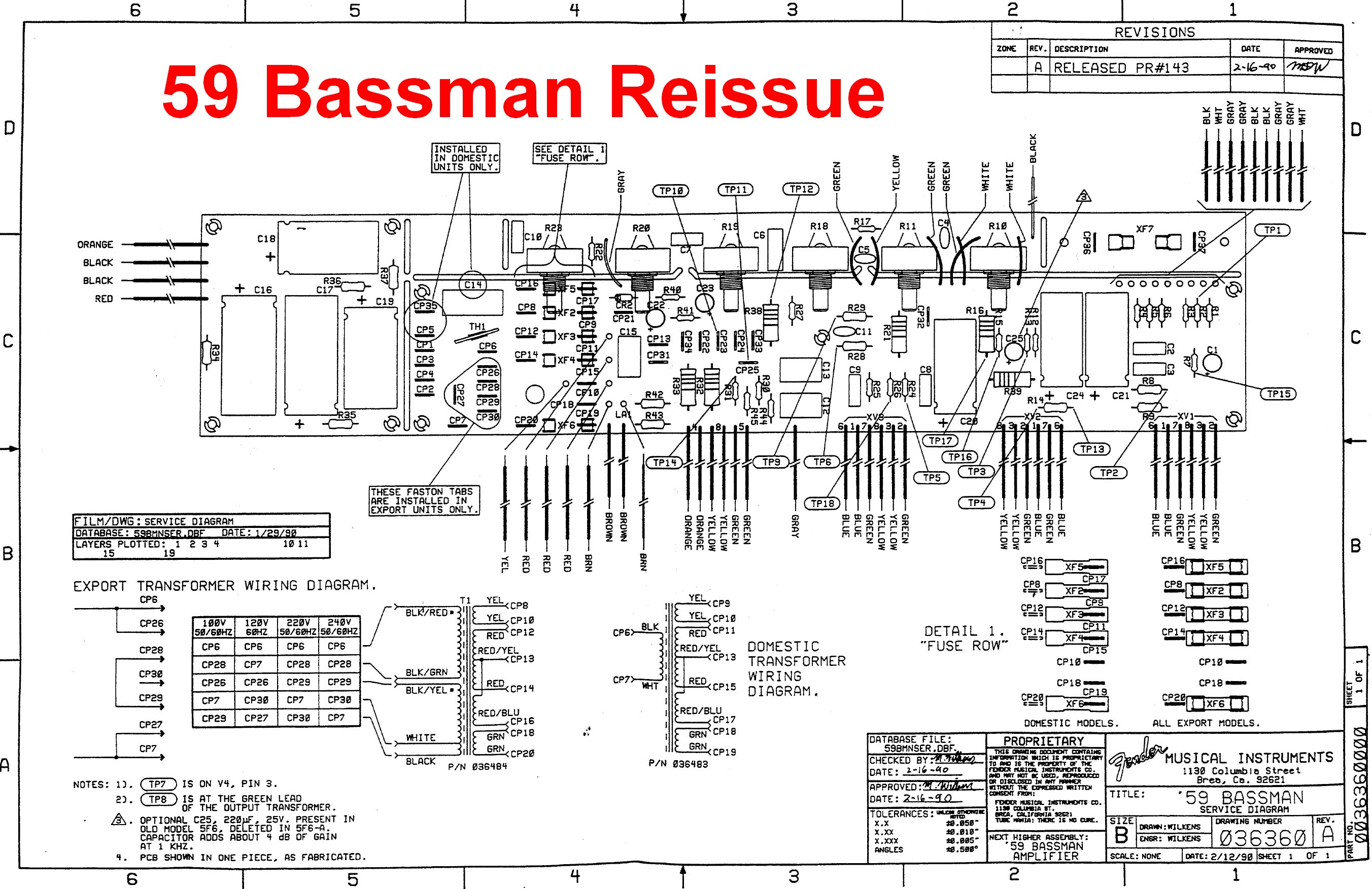
Click the image to see the hi-res version.
My BootHillAmps.com kit 5F6A Amp Head
I purchased the 5F6A kit from Dave at BootHillAmps.com and the parts sat in my basement for almost two years before I got around to building it. What a fantastic amp. I absolutely love my Bassman.
Testing My Bassman Chassis on the Bench
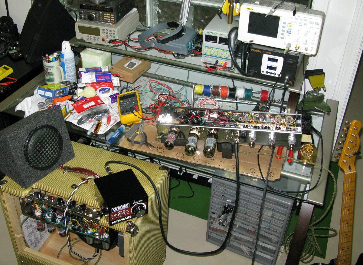
For my 5F6A build I used the exact component values shown in the original Fender schematic and layout diagram--even the crazy small 100pF bright channel bright cap. I put a 100k 2 watt resistor across the standby switch (Merlin mod) to prevent pop and inrush current so I left off the .047 600v standby switch hot side anti-pop cap. I also left out the infamous ground switch and death cap.
I went with Mercury Magnetics ToneClone+ FTBP-59M 350-0-350V power transformer and my B+ voltage is about 15 volts higher than I really wanted. I believe Mercury has a 340-0-340v ToneClone for the Bassman which would be better with my 125v wall power. The original Fender 5F6A schematic shows the power transformer as 325-0-325v so a lower HT output would be more authentic.
I'm very happy with the ToneClone+ FTBO-M output transformer with 2, 4 and 8 ohm output and the ToneClone FC-2.84 3 Henry choke. The power transformer puts out 7 amps of 6.3v heater current to safely run EL34, KT66 and KT88 power tubes.
My 5F6A Voltages
AC from the power transformer: HT = 358-0-358V RMS AC, 716V RMS AC measured wire to wire (wall voltage of 125V), Heater 6.8V RMS AC, Rectifier Heater 5.4V RMS AC
B+1 (A) Power Tube Plate supply = 449V DC
B+2 (B) Power Tube Screen supply = 449V
B+3 (C) Phase Inverter supply = 405V
B+4 Preamp supply = 336V
| V1 | V2 | V3 | V4 | V5 | V6 | |
| Pin 1 | 174 | 183 | 273 | 0 | 0 | |
| Pin 2 | 0 | 0 | 28.3 | 3.4VAC | 3.4VAC | 5.3VAC |
| Pin 3 | 2.8 | 1.4 | 47 | 451 | 449 | |
| Pin 4 | 3.4VAC | 3.4VAC | 3.4VAC | 451 | 449 | 358VAC |
| Pin 5 | 3.4VAC | 3.4VAC | 3.4VAC | -45.1 | -45.1 | |
| Pin 6 | 172 | 335 | 252 | 451 | 449 | 359VAC |
| Pin 7 | 0 | 184 | 29 | 3.4VAC | 3.4VAC | |
| Pin 8 | 2.8 | 185 | 47 | 0 | 0 | 5.3VAC/449VDC |
| Pin 9 | 3.4VAC | 3.4VAC | 3.4VAC | N/A | N/A | N/A |
Note: All voltages are DC unless specified as AC. All AC voltages are RMS, not peak or peak-to-peak.
My favorite power tubes, Tung-Sol 5881's, are biased at -45.1v on the grid, 443 plate voltage, 40.7 milliamps of plate current (measured by output transformer shunt) for 69.3% of their rated 26 watts with 70% being max safe for fixed bias Class AB operation. A pair of KT88's biased at -45.5 on the grid, 430 on the plates and 55ma of plate current for 68.7% of their rated 35 watts of plate dissipation (note how the extra current pull of the big KT88's caused the power supply plate voltage to drop). I have an ElectroHarmonix 12AY7 in V1 and Tung-Sol 12AX7's in V2 and V3.
My Homebuilt 5F6A Amp Head
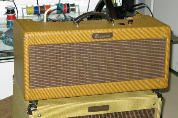
There's a 6" Eminence 620H hemp coned practice speaker behind the grill. The very nice custom lacquered tweed cab with 6" baffle was made by John Mergili of www.mergili.com and cost only $259 delivered. An empty matching 4x10" cab was quoted at $280 + shipping.
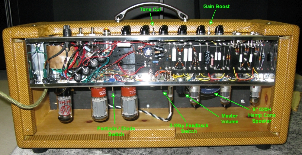
Notice the stealth Eminence 620H speaker peaking out at bottom right.
My Mods and Extra Switches
The following seven mods add versatility but are switchable so I can run the amp as a normal 5F6A. All the switches are set so IN = Normal.
Lead Channel Mod I voiced the Normal channel for a tight, modern Marshall overdrive tone but left the Bright channel unmodified.
Gain Boost Switch between the volume knobs adds a bypass cap to the V2A cathode to boost preamp gain. IN = Normal / OUT = Boost.
Raw (Tone Cut) Switch between the tone knobs removes the tone stack from the amp circuit. IN = Normal / OUT = Raw.
Trainwreck Type 3 Master Volume pot is next to V3. Full Up-Clockwise = Normal.
3-Way Negative Feedback Switch is next to the speaker jacks. IN = Normal / Center = No Feedback / OUT = JTM45.
Pentode / Triode Switch is between the power tubes and cuts output power almost in half. IN = Normal / OUT = Low Power Triode Mode .
Adjustable Bias for use with 5881, 6L6, 6V6, KT66, KT77, KT88, EL34 and 6CA7 power tubes. My power transformer has enough heater current to run the KT and EL tubes.
I also jumpered the power tubes' pins 1 & 8 together so I could run EL34 power tubes. The original Fender 5F6A layout shows these pins jumpered.
Fender 1959 Catalog Showing the 5F6-A Bassman
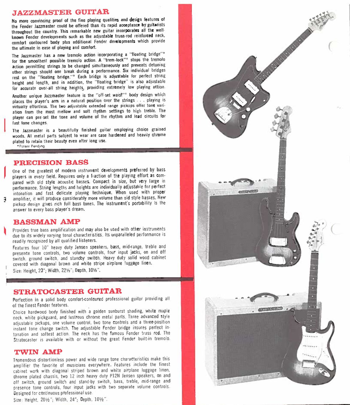
By Rob Robinette
References
RCA Corporation, RCA Receiving Tube Manual, RC30.
Merlin Blencowe, Designing Tube Preamps for Guitar and Bass, 2nd Edition.
Merlin Blencowe, Designing High-Fidelity Tube Preamps
Morgan Jones, Valve Amplifiers, 4th Edition.
Richard Kuehnel, Circuit Analysis of a Legendary Tube Amplifier: The Fender Bassman 5F6-A, 3rd Edition.
Richard Kuehnel, Vacuum Tube Circuit Design: Guitar Amplifier Preamps, 2nd Edition.
Richard Kuehnel, Vacuum Tube Circuit Design: Guitar Amplifier Power Amps
Robert C. Megantz, Design and Construction of Tube Guitar Amplifiers
Neumann & Irving, Guitar Amplifier Overdrive, A Visual Tour It's fairly technical but it's the only book written specifically about guitar amplifier overdrive. It includes many graphs to help make the material easier to understand.
T.E. Rutt, Vacuum Tube Triode Nonlinearity as Part of The Electric Guitar Sound
[ How the 5E3 Deluxe Works ] [ Deluxe Models ] [ DRRI & 68 CDR Mods ] [ Amp Troubleshooting ] [ My 5E3 Build ] [ Spice Analysis ] [ The Trainwreck Pages ] [ Fender Input Jacks ] [ B9A Prototype Boards ]